500x150x(26pieces 97mm wings) heatsink is tinny?  360x145 (14pieces 97wings) is ok for aleph 5( after 5hours in summer you can touch and stay hand as long as you wish) this monster is ok. I have no problems with heatsinks, and maybe no problems with with mountening(i will measure tomorow each mosfet temperature)
I have problem with source resitors,and with stability of DC ofset especialy in balanced mode. what grounding sheme you using for aleph x? when I conect other channel rca unbalanced amp starts hum, when only one channel is working no hum. where is a problem. I using one trafo and one bank of filtering caps.(50x 7100uf caps)
360x145 (14pieces 97wings) is ok for aleph 5( after 5hours in summer you can touch and stay hand as long as you wish) this monster is ok. I have no problems with heatsinks, and maybe no problems with with mountening(i will measure tomorow each mosfet temperature) I have problem with source resitors,and with stability of DC ofset especialy in balanced mode. what grounding sheme you using for aleph x? when I conect other channel rca unbalanced amp starts hum, when only one channel is working no hum. where is a problem. I using one trafo and one bank of filtering caps.(50x 7100uf caps)
The base of the heat sinks and the fins themselves look to be quite thin. I'll bet you notice quite a temperature change from center to each end. They appear to be made from angles bolted together, or you have bolted extruded sinks to angles. Each metal to metal junction decreases the effectiveness of the sinks.
For comparison, on a similar rail voltage AX, I will use a pair of heat sinks 220 mm wide, 220 mm high, with 20 fins - 60 mm high and 3 mm thick on a 20 mm thick base. Even then, I wish I had more so I could bring the bias up.
The DC offset will be greatly influenced by air currents around the input pair. Make some form of enclosure or blow a fan on them to stabilize their temperature.
There are lots of threads on troubleshooting ground loop issues. You have one. you can try lifting the ground on one channel's input. Are all grounds led to a common star?
I suggest you leave the heat problem alone for a moment, just keep an eye or a hand on them heatsinks, you’ll see fast enough if they get too warm.
What is important is to make one amp work, at low bias. Aim for 0.2V across the source resistors, that is about 0.5A through each mosfet. I believe the heatsinks can easily take that.
Then, try to get the output DC in line. Both from output to ground and from out+ to out-.
Out to ground is not that critical. Anything between -1 and +1V is fine. DC between OUT- and OUT+ is what the speakers see so try to match for less then 100mV to start with. Less is better.
When connected unbalanced, the –input should be grounded.
/Hugo
BobEllis said:The base of the heat sinks and the fins themselves look to be quite thin. I'll bet you notice quite a temperature change from center to each end.
yeap it is but its pretty minor..
For comparison, on a similar rail voltage AX, I will use a pair of heat sinks 220 mm wide, 220 mm high, with 20 fins - 60 mm high and 3 mm thick on a 20 mm thick base. Even then, I wish I had more so I could bring the bias up.
220x220x 60mm wings(20 pieces) ? and base is 20mm.. massive ones
playing with variuos home made heatsinks I noticed one thing- the more massive wings and base will not absorbt bigger heats. just the temperature will rise slower. and down also slower. the most important thing is surface (the bigger the better) and materials(aluminium is ok, cooper is very good) also very economic heatsinks where wings has some grooves(its rises surface much)
The DC offset will be greatly influenced by air currents around the input pair. Make some form of enclosure or blow a fan on them to stabilize their temperature.
input irfp 9610 still sits without heatsinks
There are lots of threads on troubleshooting ground loop issues. You have one. you can try lifting the ground on one channel's input. Are all grounds led to a common star?
my ground is this way, no refricters are grounded, no grounds at all just zero potential grouind from power supply conecte to both pcb gnd and from there goes to rca grounds.
also when my rca disconected the amp dc ofset goes to 1,2v and diffusors of spekers goes forward
when I conect unbalanced cables its dissaperas. if I disconect balansed - from gnd the same. Netlist said:I suggest you leave the heat problem alone for a moment, just keep an eye or a hand on them heatsinks, you’ll see fast enough if they get too warm.
What is important is to make one amp work, at low bias. Aim for 0.2V across the source resistors, that is about 0.5A through each mosfet. I believe the heatsinks can easily take that.
Then, try to get the output DC in line. Both from output to ground and from out+ to out-.
Out to ground is not that critical. Anything between -1 and +1V is fine. DC between OUT- and OUT+ is what the speakers see so try to match for less then 100mV to start with. Less is better.
When connected unbalanced, the –input should be grounded.
/Hugo
I can not get lower than 0,45v across source resitors. I can resoder and change 75kohm resitors to something lower, lets say 50kohm. but why to lower bias? I will drive woofers wchich impedanse at 30 and 75hz is 2.5-3ohm..
sound of aleph x
BTW today I listened for a 40 minutes my new aleph x. as a reference was my aleph 5. of course like every time no bass was found *its always when I am using new amp and electrolytic,after 2 wekks it will get better )
very strange sound,I can not recognize the warmth and liquidiness in high frequencies of clasic alephs amps
the resoliuton and details was farr to better than a5, and sound very neutral. but what is strange its soundstage. it is too big in both height and with. first time I complain about big soundstage but with wilson audio watt puppy 6,1,parasound dac and kimber 8tc/4tc/and silver home made interconects its just too big
and some "euphonic" feeling.. its very similar when I conect one speaker out of phase or when I am listening to phones. starnge
I will listen tomorow more.and try to balanced mode(my dac has 4x pcm 63k in fully balanced PP mode) tomorow I will se how my 1% vishay dale rs10 10w resistors will do job.obviuoly that 5% cheap resitors wasnt very good..
i found discusion about that alephs gain is too smal to drive it without preamp(somebody wanted to drive it directly from cd ot passive atennuator,just like me) and Mr. Nelson answer
"You can crank up the gain via the feedback loop as much
as you like on any Aleph."
waht does this mean? I always thought that I can lower input resitor value and get more gain by decreasing input impedanse..
"You can crank up the gain via the feedback loop as much
as you like on any Aleph."
waht does this mean? I always thought that I can lower input resitor value and get more gain by decreasing input impedanse..
Decreasing input impedance has no direct effect on gain, and may make the amp more difficult to drive.
However, the input resistors in the AX are part of the feedback loop and decreasing them will increase the gain. The same effect can be had by INcreasing the feedback resistors (the ones from the output to the inputs, typically 100K).
However, the input resistors in the AX are part of the feedback loop and decreasing them will increase the gain. The same effect can be had by INcreasing the feedback resistors (the ones from the output to the inputs, typically 100K).
I mean input resistors.so better decrease input resistors or increase feedback resistors. I have pretty beefy DAC outputs but it doesnt drive aleph x to max. if do this mod how will change my aleph x impedanse? manufacturere of my dac recomends minimum 10k ohm load. I am planing to feed 2 pieces aleph via balanced mode.
Which route is better for you? You answered your own question if you think about it:
You don't want to decrease the input impedance of your amps, so increase the feedback resistors. There is a limit to how much you can increase the gain, because the amp itself has finite open loop gain. The sound character may change noticeably if you change the gain too much.
A good preamp wouldn't be a bad idea. XBOSOZ comes to mind, and there are boards available currently...
IIRC, in the A75 article NP explained how to calculate balanced input impedance.
elviukai said:... manufacturere of my dac recomends minimum 10k ohm load. I am planing to feed 2 pieces aleph via balanced mode.
You don't want to decrease the input impedance of your amps, so increase the feedback resistors. There is a limit to how much you can increase the gain, because the amp itself has finite open loop gain. The sound character may change noticeably if you change the gain too much.
A good preamp wouldn't be a bad idea. XBOSOZ comes to mind, and there are boards available currently...
IIRC, in the A75 article NP explained how to calculate balanced input impedance.
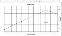
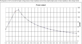
hi today I used alepx x excel calculation and with 8 fets , 20,4V secondaries ,25V at fets, 0,39ohm resistors (0.48V across them) I am getting figure like this. no wonder that there is no low frequency response with my watt puppies which have 2-3ohms in bass region!
Attachments
50% current gain is "standard" - most people shoot for that.
If you look at cell B33 of the spreadsheet it says you want a 0R4 source resistor with 16 FETs - you just increase the resistance of the pots in the current sources until you get .5V across them.
You will need heat sinks that give you an R theta of 0.1K/W or less. I suspect that your current sinks are nowhere near up to the task.
hi Bob thanks again for help. in excel calculations I can not change b33 cell value(LOCKED) ONLY B34
AS MUCH i CHANGE B34 VALUE i GET DIFERENT VOLTAGES ACROSS SOURCE resistors and ampers.
which resitors I need to change to increase bias. I have just bought bunch of pretty 50k ohm multiturn pots want to buy new. can I just put in series some resisitanse for them and with what values I should play? or I can change some resistors in schemtic.
BTW I tried to rise input sensitivity and changed 100kohm resistor to 130khom. result 15V ofset
another trouble(for impatience) I already buy 1500w 5x 20V secondaries transformers. how I can lower voltage of trafos I think I would nedd avout 12-14V secondaries (maybe aply inductor before caps LCCC?)
regarding my heatsinks. they dissipate with no problems 250W channel but 300w after 3 hours are to hot to touch more than 2-3sec.
I desided play safely and for prototype build huge enclosure with heatsinks- height 220 lenght 600 fins 40pieces of 4mm, base from 9mm. that woul let me dissipate arround 650-700 single or 1300-1400w both channels. without problems. I could use bigger rails witht his heatsinks but I do not need hundreds of wats. 80-100W for 8ohm and 200w for 2.5ohm just be fine.
Cell B33 is the spreadsheet telling you what source resistor you need to achieve the desired bias. You adjust the variable resistors in the aleph current sources (not the one in the ccs that feeds the inputs.) As you increase the value of that variable resistor your source resistor voltage should increase.
Cell B34 is where you input the standard value closest to B33. You then see the power dissipated there in the cells below.
An L input filter would definitely lower the rail voltage. Find Duncan Amplification's PSU designer and simulate your chosen arrangement.
If you can hold your hands on the heat sinks for 2-3 seconds they are probably at around 55C. With standard isolators (Use .7 in B68 and B69) you should be OK. You can always use a small fan to help cool.
yap I understand it after worked more with this program. lets say I want to up tje bias with parareling devices packs(mosfet, source resistor, 221ohm resistor) from 8 to 16. that means that I am already getting more bias with standart values. do I need change any other components in schematic? I am studying at the moment grolins and kristjan schematic differences. grolins has only 4 devices but highly biased and kristijan 8devices with looks like also 5 amps bias. pots are 100kohm to grolins and 50kohm to kristijan schematic.
- Status
- This old topic is closed. If you want to reopen this topic, contact a moderator using the "Report Post" button.
- Home
- Amplifiers
- Pass Labs
- 10 pieces aleph x and non of theese working