I got the complete kit a few days ago. That kit contains 2 mainboards, 2 MC pre boards and 2 PSU boards. This threat is about the MC pre boards, so that is also what my question is about. Once again, Why wasn't "Star" not connected to "Star1" when there is room on the PCB to do so?
Is it better to connect "Star1" to GND and leave "Star" connected to 0V (so not shorting 0V to GND via this connection)?
That doesn't sound like a description of what's available from Pass DIY, so it would appear you've bought a preamp from another source? Where did you get it, and what is it? Can you post photos? We'll need more information before anyone will be able to answer your question.
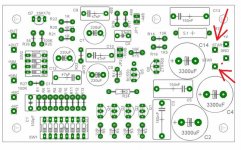
I got the kit from a friend. The board I'm talking about is the board from page 3, posting #23 of this topic. I attached the drawing of that board and marked the "Star" and "Star1" point with a red arrow.
The qoute in my first post is from posting #38 of this topic.
My question remains. Why were "Star" and "Star1" not connected in the PCB layout?
The qoute in my first post is from posting #38 of this topic.
My question remains. Why were "Star" and "Star1" not connected in the PCB layout?
Attachments
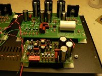
Here's the Aleph-Ono MC-stage. I have used Black Gates as coupling caps.
Fox, did you keep the original values? (3 x 220 µF and 47 nF MKP in parallel)
What about varying these values? Will it gain a measurable effect at the lower end?
I'd like to replace these with 330 µF or even 470 µF Silmic IIs and Wima FKP3 in parallel.
This is the correct schematic.
Illias (and all others),
 if you still visit this topic one question:
C7, C9 and C11 (all 220 µF) seem a bit huge to me. At least C11, which is followed
by the 47 Kohm of the Pearl's MM input, shouldn't require more than a couple of µF,
say max. 10 µF to be safe. Meaning a MKT/MKS would do the job.
Please correct me if I'm wrong.

I'm going to replace the Pana FCs with Silmic IIs (I already have) and the bypass
PP Panas with Wima FKP3s. But the question of the proper values remains. If a MKT
oder even poly would do for C11, this most likely would be a benefit.
Before I do my own experiments (and solder several times on the boards) I'd highly
appreciate some profound comments.

Attachments
I've had my Pearl 1 running for a few years. A few weeks ago I noticed a channel imbalance (left side quieter than right).
The voltage drop across all the 22 ohm 2sk170 ballast resistors in both channels is 107 mv. Across R25 in the left channel it is 290 mv and 118 mv in the right. Does this sound like a 2SK389 gone bad?
The voltage drop across all the 22 ohm 2sk170 ballast resistors in both channels is 107 mv. Across R25 in the left channel it is 290 mv and 118 mv in the right. Does this sound like a 2SK389 gone bad?
Pearl Multi -- putting the RIAA network on a daughter card, using NXP JFETs:
An externally hosted image should be here but it was not working when we last tested it.
I made a couple of changes -- insert a small choke on each gate of the input JFETs and separate source resistors. The line-out JFETs could use 100R on the gates of the BF862's. The board has a compensation network for RIAA and NAB equalization, just use a pair of aircraft shears to cut along the line.
Interesting that 100K||1.1K gives an almost exact value for R2 in the passive RIAA network.
Interesting that 100K||1.1K gives an almost exact value for R2 in the passive RIAA network.
An externally hosted image should be here but it was not working when we last tested it.
An externally hosted image should be here but it was not working when we last tested it.
An externally hosted image should be here but it was not working when we last tested it.
- Status
- This old topic is closed. If you want to reopen this topic, contact a moderator using the "Report Post" button.
- Home
- Amplifiers
- Pass Labs
- Pearl MC Pre-Preamp