Hi all,
I have a little prolem with my aleph X.
Here is the problem i face :
I power on my aleph X. Power supply provides around 21Vdc to the board. Voltage through all source resistors is 0.5V , all is heating nicely until 30 seconds after power on.
The power supply voltage drop to 8 V and MOSFETs (IRF240) stop heating.!!

What is this?? What's wrong with my Amp?
Thanks for your help in advance
Loic
schematic i use enclosed + PCB i have
http://jppelan.free.fr/HC/ALEPH_X/ax-pcb.jpg
I have a little prolem with my aleph X.
Here is the problem i face :
I power on my aleph X. Power supply provides around 21Vdc to the board. Voltage through all source resistors is 0.5V , all is heating nicely until 30 seconds after power on.
The power supply voltage drop to 8 V and MOSFETs (IRF240) stop heating.!!
What is this?? What's wrong with my Amp?
Thanks for your help in advance
Loic
schematic i use enclosed + PCB i have
http://jppelan.free.fr/HC/ALEPH_X/ax-pcb.jpg
Attachments
Banned
Joined 2002
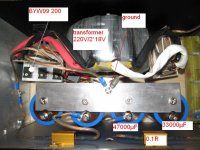
here the picture of my PSU. i have recifier ( 18Vac - BYW99 200 then 47000µF then 0.1R then 33000V )
I Tried to run my PSU not connected to the Board : It keeps 24.5V on V+ and V- with a difference of 0.05V betw. V+and V- voltage.
Voltage do not drop even after minutes working (not connected to the board).
Loic
I Tried to run my PSU not connected to the Board : It keeps 24.5V on V+ and V- with a difference of 0.05V betw. V+and V- voltage.
Voltage do not drop even after minutes working (not connected to the board).
Loic
Attachments
Loic,
the big alu plate you used seems to be dangerously close to the +. Watch out!
If there were a short, the PSU wouldn't work on his own.
This is how I wired the PSU in my AlephX:
http://www.diyaudio.com/forums/showthread.php?postid=194297#post194297
The main difference is other rectifiers, and a CRCRC instead of CRC in your amp. Can you confirm the similarities and the way you wired up your Aleph? The ground connection should of course go the star ground of the PCB.
Is this power supply for both channels or only one monoblock?
/Hugo
netlist
Yes my PSU is looking like yours.
here my schematic :
http://s37.photobucket.com/albums/e99/veritelo/?action=view¤t=LOIC_PS.jpg
I replace capacitors by 1* 33000 then 0.1 R then 47000µf
Other items of my PSU are identical to the schematic
thermistance is a 22 ohm. My PSU is for both channels.
I connect the ground of PCBs to the aluminium plate ground.
V+ of the pcb to + of capacitor(red cross on my PSU photo)
; - of capacitor screwed on alu plate
V- of the pcb to - of capacitor(red - on my PSU photo)
; + of capacitor screwed on alu plate
For information :
Wtih Vr2 at 140 Ohm and Vr1 /Vr3 at 0 ohm
i measured (few second after power on)
between PCB ground and OUT + : 10v decreasing with time
between PCB Ground and OUT- : 5v decreasing with time
Loic
Blues
In order to lower risks i have connected only the 47000µF capacitor, not using the 33000µf for the moment.
So i have + 18Vac from transfo to the rectifier input then rectifier output to 0.1R then 47000µf. Resistors are NOT connected to ground plate.
That mean, for the moment , i'm in a RC configuration.
Is it a problem source?
Loic
What's your NTC ? Rated for your primary current ?
Does the Xformer heat up during the first 30 s of normal behavior ?
Any info about a thermal fuse in the trafo ?
Unplug the amps from the supply, remove (bridge) the NTC, and hook up some power resistors to the supply's output, in order to draw the same current than the amps. Does the strange behavior still show up ?
Same thing when the NTC's in ?
C9 and C10 seem to be polypropylene caps. It looks like they were heated up too much.
These caps tend to melt instantly when the foil is touched with the soldering iron. The result is a dead short capacitor. If my assumption is correct, replace them.
Also, check your soldering work. On some pictures I see cold joints, especially on the bigger wires.
As Cheff said, connect something like a 20ohm/50W between + and ground and another one between – and ground. See if the PSU can supply that power. At 24.5V a 20 ohm R will pull a current of 1.2A.
/Hugo
Cheffdegarr
I have measured Voltage across 0.1 ohm Resistor of my PSU during first seconds of normal amp. work :
Voltage drop is 0.61V on V+ side resistor and 0.56V on V- resistor side.
That mean a current draws on V+ side is 6.1 A and 5.6A V- side.
Is it normal ?
I notice also that one of my BYW99 rectifier diode is getting hoter than the others. May i check this diode when PSU has dropped to 8V?
I have checked my NTC values : it is an EPCOS rated for 220 V (265 Vcc) The C830 model in datasheet .http://www.farnell.com/datasheets/62080.pdf
Nevertheless, I will do a try without NTC
Netlist, C9 and C10 a styroflex capacitors (polystyrene) one. I have replaced them by new one and removed all unnecessary capacitors (including wima ones) and kept only C1 C3 C5 C6 C9 C10.
With no more success.
Next step to try without NTC and try with 20ohm 50 W resistors
thx Loic
Loic, any progress?
The power test is crucial. The value of the power resistors isn't.
anything between 15 and 25ohm or so will do as a basic test, as long as their power rating is high enough.
The diode warming up is not good. Check every one of them and see if the polarity and wiring is correct.
/Hugo")
The power test is crucial. The value of the power resistors isn't.
anything between 15 and 25ohm or so will do as a basic test, as long as their power rating is high enough.
The diode warming up is not good. Check every one of them and see if the polarity and wiring is correct.
/Hugo
Gentlemen
Good news
The Problem is on my NTC. With NTC by passed , all is doing well.
My NTC is on primary side on my transfo.
The NTC i have is rated 120°c and 1.2A for 250 V.
My Amp is biased at 6A under 20V.
Is my NTC current rating sufficient? What can i use as a good alternative? a soft start circuit ? Is there a schematic or a ready to make product available?
Loic
Loic,
Glad you found it
Have you listened to the amps ?
Two more links to help you calculate your NTC ratings :
This one and this other one
Hope this helps
Glad you found it
Have you listened to the amps
?Two more links to help you calculate your NTC ratings :
This one and this other one
Hope this helps
gentlemen
i have listened to my amp in stereo :WOWWWWWWWWW.
A real surprise to me !!! great sound , wide and deep scene.
Happy man i am..
A question now : i have seen some guys use input caps for input signal.
I saw Neslon said that we shall avoid the use of the input cap as much as^possible but what the use of having it. What is its effect ?
For the moment i'm connected unbalanced.
Loic
That is great news.
The input cap is there to prevent any DC component present at the input from appearing amplified at the output.
Your speakers don't like DC as you probably will know.
I your preamp has a very low DC offset, you can do without the input cap. Since you can adjust the AlephX to your needs, it's easy to connect your preamp and trim for the lowest DC value at the output. No need for a cap then.
/Hugo
Netlist
For the moment my CD player is connected directly to the amp. Volume can be modified within the cd palyer with remote control.
What are max values of Offset between Outputs terminals?
I measured 0.022v on one side and 0.018V on the other.
Second point, i tried seting up the variable constant current source, (r12/r34 pots) following the WIKI.
The problem is i measure ZERO Vac through R2/R3 resistors and even R5 on both sides of the amp.
CD player connected to input and speaker connected to output. I tried to turn R12 or R34 with no visible effect.?
R2/R3/R5 are all 0.47 Ohm.
loic
- Status
- This old topic is closed. If you want to reopen this topic, contact a moderator using the "Report Post" button.
- Home
- Amplifiers
- Pass Labs
- debuging aleph x