As I recall from the original article, the Zen effort is an explorationGRollins said:Being two stages, it probably doesn't count as a true Zen amplifier any more, but speakers don't care.
in simplicity, and I don't see why this wouldn't qualify.
Look at this, it's 1 pcb. You may stack, for example, 5 units, on 1 heat sink. Parallel everything except for the speaker outs. Then, calibrate the 4 pots so that all the units match. Finally, bridge the speaker outputs & voila...
Non-VGS matched mosfets now matched.
Non-VGS matched mosfets now matched.
Attachments
Nelson Pass said:
As I recall from the original article, the Zen effort is an exploration
in simplicity, and I don't see why this wouldn't qualify.
And if we compare Grey's output stage+bosoz with a zen+bosoz, we still have the same "keep it simple" idea
Brian Guralnick said:
Instead of trying to steal this thread, just post the question as a new topic, & if Mr Nelson feels up to it, I'm sure he'll add photos.
No one here is stealing threads

How much matching do you want? It's pretty easy to getBrian Guralnick said:Non-VGS matched mosfets now matched.
10 mV. we do it all day long. My standard max for output
DC is 100 mV, although some might say that's too much, only
rarely is it a real issue.
Brian Guralnick said:Look at this, it's 1 pcb. You may stack, for example, 5 units, on 1 heat sink. Parallel everything except for the speaker outs. Then, calibrate the 4 pots so that all the units match. Finally, bridge the speaker outputs & voila...
Non-VGS matched mosfets now matched.
Brian,
I can follow your reasoning, but this is a very dangerous course of action. Even for a single, having 3 or 4 pots in an amp with all the drifting and aging is asking for problems. And parallelling 4 or 5 means that as soon as you close the lid after adjusting, they will start to drift apart, and one or the other will load down the rest, and it'll be a real mess.
Generally, it is considered a sign of competent design when no adjustments are needed, while still using unselected standard components. YMMV.
Jan Didden
Nelson Pass said:
How much matching do you want? It's pretty easy to get
10 mV. we do it all day long. My standard max for output
DC is 100 mV, although some might say that's too much, only
rarely is it a real issue.
100mv with many designs is not an issue. It's also easy to achieve when dealing with more than 10 mosfets. My illustrated circuit with the 20 turn precision pots allows you to adjust many modules, say 4 for example, down to 10mv, of less. Now, paralleling these modules without output series resistors for the speaker drive should allow for a balanced load across all the 8-10 mosfets a DIYer may have purchased.
Example PCB... (Another VIA-LESS design)
Attachments
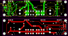
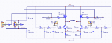
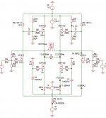
When stacking this PCB vertically, you just need to feed 12aug solid core wires through CN1 & CN3, 18aug for CN5. On the top PCB, put in standard terminals for CN2 & CN4 & CN6.
RP3 & RP4 calibrates the CCS for Q3&4, TP1 & TP2 is there to measure the emitter resistor voltage.
RP1 & RP2 calibrates the output offset of mosfet Q1 & Q2.
RP3 & RP4 calibrates the CCS for Q3&4, TP1 & TP2 is there to measure the emitter resistor voltage.
RP1 & RP2 calibrates the output offset of mosfet Q1 & Q2.
janneman said:
Brian,
I can follow your reasoning, but this is a very dangerous course of action. Even for a single, having 3 or 4 pots in an amp with all the drifting and aging is asking for problems. And parallelling 4 or 5 means that as soon as you close the lid after adjusting, they will start to drift apart, and one or the other will load down the rest, and it'll be a real mess.
Generally, it is considered a sign of competent design when no adjustments are needed, while still using unselected standard components. YMMV.
Jan Didden
That's why I built this device:
http://www.diyaudio.com/forums/showthread.php?postid=257957#post257957
janneman said:
Brian,
I can follow your reasoning, but this is a very dangerous course of action. Even for a single, having 3 or 4 pots in an amp with all the drifting and aging is asking for problems.
Jan Didden
Ok, got rid of the pots.
For the mosfet offset voltage, I'll just match the mosfets.
For the CCS side, I added an NPN transistor across (1 side example) Q3's emitter, base & V-15. Now, when the voltage across R9 is large enough, the base of Q3 will be pulled down creating a further regulated CCS.
SE SOZ
I have a stupid question:
Is it possible to create a realy single ended design from the original SOZ circuit? (I mean not balanced) For example if would like to hear more 2nd harmonic distorsion. ( a kind of "tube like sound"). I know I can operate the SOZ from SE source, but it waste the one half of the circuit.
Thanks!
The main problem you'd face is the DC offset. If you tie one end of the speaker to half of a SOZ, what do you tie the other terminal to? The usual answer would be ground. The problem there is that the DC offset from the Drain of the MOSFET to ground would cook the voice coil in short order.
Two possibilities occur to me. The easy way to do it would be to capacitor couple the output to the speaker. With a large enough cap, you'd get the music, but not the DC. In essence, you'd be building an original Zen, but using the 8 ohm resistor above the Drain as a sloppy current source. It'd work.
The other possibility is to contrive a device on the other side that will accept the signal, but has a DC potential equal to that of the driven side. That way the DC would cancel out and you'd be left with the music. At that point, you might as well let the "accepting" side be the other half of the SOZ, and you're back where you started. Might as well drive the "accepting" side and be done with it.
Note that if you take away half of a SOZ, the power will drop by a factor of four.
Grey
Re: SE SOZ
ZV4.
I think you just want a Zen, or one of its variants, such asTyimo said:Is it possible to create a realy single ended design from the original SOZ circuit? (I mean not balanced) For example if would like to hear more 2nd harmonic distorsion. ( a kind of "tube like sound"). I know I can operate the SOZ from SE source, but it waste the one half of the circuit.
ZV4.
Mr. Pass!
I built already the Zen and a Balanced Zen version from Kristijan Kljucaric. I enjoy the music with the Zens very much, but the SOZ design is fascinating me. I just thought on a not balanced SOZ, with it's simplicit...,but I think I have to try the original SOZ as it is.
Well, may be with 1 H inductors in the PSU....")
I built already the Zen and a Balanced Zen version from Kristijan Kljucaric. I enjoy the music with the Zens very much, but the SOZ design is fascinating me. I just thought on a not balanced SOZ, with it's simplicit...,but I think I have to try the original SOZ as it is.
Well, may be with 1 H inductors in the PSU....
The PMPXA
Thanks Gray.
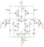
"Poor Man's Pass (Labs) X Amplifier" I like that phrase.
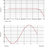
I have made a first shot in the sim. It looks pretty nice. And the title coud be The PMPXA.
GRollins said:At that point, it becomes a fairly easy task to "X" the circuit. Presto! A poor man's Pass Labs X amplifier. All in two stages and with minimal parts count.
Grey
Thanks Gray.
"Poor Man's Pass (Labs) X Amplifier" I like that phrase.
I have made a first shot in the sim. It looks pretty nice. And the title coud be The PMPXA.
Attachments
- Status
- This old topic is closed. If you want to reopen this topic, contact a moderator using the "Report Post" button.
- Home
- Amplifiers
- Pass Labs
- Pass Son of Zen w/current sources (etc.)