R-K Rønningstad said:
+/- 15 V for the opamp? I think the original's opamp runs off 0 and +24V. Or?
I agree with you Rolv, that’s what I thought the opamp on the original works from the main rail only.
I did a small search on the spec sheets for a couple of opamp to see what they have to say about single rail operation. Most don’t even touch the matter and one of them says that on certain conditions the device could get unstable.
In the other hand I had some misconception regarding single rail operation for opamps too, and decided to read a bit on the subject. According to Joseph J. Carr if we bias the non inverting terminal to half the rail voltage it can work with no problems. For this Nelson has shown the way and its already biased with R6/R7 on the circuits we have seen on this thread. So we have it all done. The one thing missing on the PCB is actually eliminating C15 and C14 and grounding the –V rail connection from the opamp.
We will follow then NP route and use the one rail supply then. Some changes are needed on the PCB and of course no need now for the opamp supply. Good Lord!!!

Of course, in 2006, we would maybe like to have a preamp run off +/- rails. Maybe Nelson himself would have made the NS10 that way today. Who knows? Only speculations of course. My point is, of course, that if we change the design from single to dual rails, or other things, it is not a NS10 anymore. Maybe a NS10 variation. Changing transistors from one NPN to another, or the opamp from one to another, in my opinion keeps it as an NS10. But if you change to split rails, from BJT to JFET, etc, it is not a NS10 anymore. Be that as it may, changing the it to what I call "not-NS10" should of course still be allowed!  SO enjoy your NS10 variations.
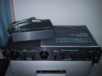
BTW I found some 800A and 800S pictures. I'll post them one of these days...
RK
SO enjoy your NS10 variations. BTW I found some 800A and 800S pictures. I'll post them one of these days...
RK
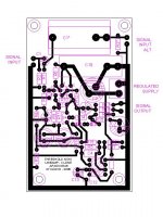
On this layout I have include the possibility to use a film cap at the input. Also we have the possibility to use two 220u for C5 or one 440u as the new schema requires.
The Opamp now is supplied by the same rail as the lineamp. No need then for the extra PSU supply for this devise.
The overall board size has increase to 2.146 X 3.556” (55 X 90 mm) to give space for the alternative input cap, I think most will welcome this addition.
PDF’s for the copper side of the boards are coming soon.
Attachments
Thanks guysCongrats Steen... one of us....
I am looking forward to make it shine as new again.
Jacco, dont worry about the Lovoltech's, they are on their way to me at this point. It takes max 2 weeks for them to arrive. I figure those guys, are crossing the Atlantic in a rowing boat
Steen
steenoe said:Thanks guys
I am looking forward to make it shine as new again.
Jacco, dont worry about the Lovoltech's, they are on their way to me at this point. It takes max 2 weeks for them to arrive. I figure those guys, are crossing the Atlantic in a rowing boat
Steen
now YOU can measure everything and post here

btw-besides all Zen iterations you build in this very moment-what's happening with your Babelfish?
steenoe said:Thanks guys
I am looking forward to make it shine as new again.
I bet you will.
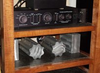
Beautiful pristine set Steen, let’s see the guts of that preamp with some pic’s.
Congratulations and enjoy!!!
I dont dare to built itwhat's happening with your Babelfish?
I have a suspicion that it will sound so great that there will be no excuses left for building another amp Terrible situation On a serious note, I will get around to it. I have a sneaking plan, to trade a pair of your nice boards for some components
 Thanks. I will post inside pictures shortly. I am a bit busy right nowCongratulations and enjoy!!!
Steen
steenoe said:
I dont dare to built it
Steen
ya know-all this is not quest for ultimate amp-more like "I'm making another amp for another room "
at least for me...
now I feel little boring with all this SS,I must make some spk cabinets and few other things,like LR RIAA eq phono section (with toobz ,naturally) and to finish long time dreamed project with trioded 307A toobz in PP
In a meantime one friend will make nice wooden box for my Babelfish J
regarding sneaking plan-I'm open for all transactions in form of "favor between friends"......hehe-especially when Oly is man with hands in acid,not me
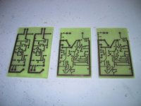
As you may have guessed I have been procrastinating for some time to post the PCB artwork for both the gain circuit and the regulator proposed.
These ones are from the component side but anyone needing it from the copper side just let me know to prepare them.
This one is for the line preamp gain circuit from the “COMPONENT SIDE”
These ones are from the component side but anyone needing it from the copper side just let me know to prepare them.
This one is for the line preamp gain circuit from the “COMPONENT SIDE”
Attachments
- Status
- This old topic is closed. If you want to reopen this topic, contact a moderator using the "Report Post" button.
- Home
- Amplifiers
- Pass Labs
- Threshold NS10 Lineamp PCB