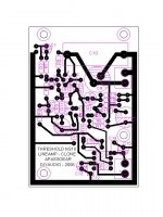
I decided to open yet another NS10 thread, this one is about building a lineamp as close as possible to the original thing with some update ideas.
This has been possible thanks to R-K (Rolv Karsten) who posted a schematic he kept for 27 years that appeared to be faithful to the original in words of Nelson Pass, besides that there were many other valuable contributions such as close up pictures of the naked boards (sans cans) of the line and RIAA PCB’s by Malotron and others. Thanks to all you great guys again.
http://www.diyaudio.com/forums/showthread.php?s=&threadid=67915&perpage=10&pagenumber=49
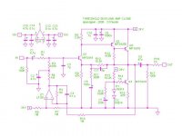
The idea behind this layout might not be for everyone since I took some “non audiophile” route regarding input and output caps which are not MKP’s but had my reason to it. Laying film caps on the board crated an awful appearance and did not look neat and ended with a big PCB for each channel. So I decided to keep the original spirit and go with lytics and thought that today’s caps are way better than 25 or 30 years ago, so why not?... use some BG or Panasonic FC’s which are way better than the old ones and in some cases being preferred to film caps by some DIY’s. The only big film cap is at the rail decoupling.
Since I wanted short traces and a compact layout I also decided to use the smaller ½ W resistors with an over all length of 0.360” (9.15mm) so no Dales RD-55’s, though I know in some places on the layout it is possible to add longer lead resistor and could add some pads, but for the time being only short resistors are possible.
All 3 signal BJT are as close as possible and the overall signal path is as short as it gets with these type and size of components which was one of the premises I started with, so I expect that the overall performance of this layout be quite good.
The overall size of the PCB is 3.110 X 2.125” (79 X 54 mm) one sided and uses no jumpers so its easy to etch and build. Most of the traces are 0.035” (0.89 mm) smaller pads are 0.080” (2mm) really don’t know how difficult could be to etch this by oneself with the regular photocopy transfer process. Any ideas?
Related to the bias opamp I decided it should have double rails for best stability and this enable to use any type with standard pinout you may have at hand, rails then should be 18/15 +-V. It’s a single unit DIP so one on each channel as the Master did.
I will welcome all suggestions so please chip in to make this layout better.
This has been possible thanks to R-K (Rolv Karsten) who posted a schematic he kept for 27 years that appeared to be faithful to the original in words of Nelson Pass, besides that there were many other valuable contributions such as close up pictures of the naked boards (sans cans) of the line and RIAA PCB’s by Malotron and others. Thanks to all you great guys again.
http://www.diyaudio.com/forums/showthread.php?s=&threadid=67915&perpage=10&pagenumber=49
The idea behind this layout might not be for everyone since I took some “non audiophile” route regarding input and output caps which are not MKP’s but had my reason to it. Laying film caps on the board crated an awful appearance and did not look neat and ended with a big PCB for each channel. So I decided to keep the original spirit and go with lytics and thought that today’s caps are way better than 25 or 30 years ago, so why not?... use some BG or Panasonic FC’s which are way better than the old ones and in some cases being preferred to film caps by some DIY’s. The only big film cap is at the rail decoupling.
Since I wanted short traces and a compact layout I also decided to use the smaller ½ W resistors with an over all length of 0.360” (9.15mm) so no Dales RD-55’s, though I know in some places on the layout it is possible to add longer lead resistor and could add some pads, but for the time being only short resistors are possible.
All 3 signal BJT are as close as possible and the overall signal path is as short as it gets with these type and size of components which was one of the premises I started with, so I expect that the overall performance of this layout be quite good.
The overall size of the PCB is 3.110 X 2.125” (79 X 54 mm) one sided and uses no jumpers so its easy to etch and build. Most of the traces are 0.035” (0.89 mm) smaller pads are 0.080” (2mm) really don’t know how difficult could be to etch this by oneself with the regular photocopy transfer process. Any ideas?
Related to the bias opamp I decided it should have double rails for best stability and this enable to use any type with standard pinout you may have at hand, rails then should be 18/15 +-V. It’s a single unit DIP so one on each channel as the Master did.
I will welcome all suggestions so please chip in to make this layout better.
Attachments

Great work Tony") Thats a nice board layout.
Thats a nice board layout.
Even though our other NS10 "clone" sounds really great, I agree that its much more fun to have a closer clone, like yours.
What do you have in mind for the PSU?
I am getting a Threshold NS10 this week. I convinced the owner that it would be better off at my place. Cant wait to get my hands on it. I am lucky enough that it comes with the moving coil box and the manual.
Steen
Thats a nice board layout.Even though our other NS10 "clone" sounds really great, I agree that its much more fun to have a closer clone, like yours.
What do you have in mind for the PSU?
I am getting a Threshold NS10 this week. I convinced the owner that it would be better off at my place. Cant wait to get my hands on it. I am lucky enough that it comes with the moving coil box and the manual.
Steen
steenoe said:Great work Tony
Even though our other NS10 "clone" sounds really great, I agree that its much more fun to have a closer clone, like yours.
What do you have in mind for the PSU?
I am getting a Threshold NS10 this week. I convinced the owner that it would be better off at my place. Cant wait to get my hands on it. I am lucky enough that it comes with the moving coil box and the manual.
Steen
it's always nice to have piece of history,especially when it's working and when it works jolly good
I hate ya,ya lucky bstrd!

Ipanema said:Hi,
Would NS10 be able to drive a 32ohms headphone? Any modification needed?
Thanks.
The NS10 has about 1K output impedance and low power so it wont drive any headphone. For this you would need to add a buffer to the output.
I don't have a ready solution for this, but will think about it.
If you only need is a headphone driver it will be best to tackle an amp that was specificaly design for this purpose, there are many projects on the forum you could try.
Hope you find a solution
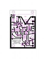
Here is an updated version of the layout.
I have added R20 to test loading a bit the Opamp, which of course is optional. This ideas come from Walter Jung and John Curl.
R19 has change position to clean traces arround the Opamp.
All traces are now 1mm which would be easier to etch.
I will follow up with a corrected schematic
I have added R20 to test loading a bit the Opamp, which of course is optional. This ideas come from Walter Jung and John Curl.
R19 has change position to clean traces arround the Opamp.
All traces are now 1mm which would be easier to etch.
I will follow up with a corrected schematic
Attachments
Even though our other NS10 "clone" sounds really great, I agree that its much more fun to have a closer clone, like yours.
Anyone who has built the "original" NS10, please inform how it sounds
I've been thinking about the original NS10 schematic that RK has posted (Thanks to RK). I think it will sound quite different from the "clone". I haven't built it, though.
First is the CCS (Q4 in the above schematic) as load. This will give less "distortion". Wheter you will like sound with more or less distortion, you should try both of them
The value of R8. With bipolar as Q1, 3k3 will give quite clean "noise" characteristic. I've been confused about this myself.
I refer to using Jfet as Q1. John Curl said that there existed phenomenon of "starving for current" when using Jfet. I experimented with this and appears that when Jfet biased with very low current (uA), it gives very noisy operating characteristic. You can read this in any small Jfet datasheet, in the first uA, Jfets always the noisiest, and very high peak noise in this area.
I use 10K for R8 and 2SK30 for Q1. For me (not speaking for anyone else
) this sounds very good. I've wonder why is this "wrong" implementation (to textbooks ie: noisiest) seems to sound better to me? The "correct" way to use Jfet for Q1 is biasing it very close to it's Idss (that is below 2k2 for R8). Later I don't care if textbook blames me of how I use this Jfet (starving for current), cause I feel it just sounds good Then I think, LP's have very big noise too (compare music to "silence" noise), and still many still take LP as the best sound source, eventhough it is the most noisiest.
That would be ThresholdAnyone who has built the "original" NS10, please inform how it sounds
Interesting points on the J-fet implementation, Lumanauw. I think I will try and test some of your ideas this weekend. I have some of the 2sk30's on hand.
Tony that board looks great, nice and tidy layout. You are more than welcome to post a pdf to scale of the copperside
Steen
lumanauw:
i agree with steenoe; interesting comments on use of JFET.
just curious if you have tried a JFET that has a lower IDSS than the 2SK30 to see that changes the sound for you in a positive or negative way? i don't know the 2SK30 specs offhand - i was thinking maybe a 2N5457 or 1/2 of a U404 (don't rememeber the single version). i think it's possible that a part designed for lower IDSS "MAY" have "better" performance/specs at lower currents in your application...
mlloyd1
Lumanauw,
Nice to have you around very interesting experience with the jfet you mention, I would like to test myself some of these ideas as the time comes. Guess, as you say that the load for Q1 (R8) will make a lot of difference since we are changing operating parameters of the device.
I’m quite anxious to start testing this “original” topology and see how much can we squeeze out of it and of course test the jfet at Q1. In your opinion, which of the small signal Toshiba’s would be your first and second pick for Q1?
As you may remember a lot has been discuss around the best type of PSU for the NS10, and Steen did try some different supply’s and in his opinion the shunt reg was by far the best sounding one but he did encounter noise problems with it.
Due to Steen experiences I started following the Blowtorch thread with great interest, mainly on shunt PSU topics to see if I learned something “simple” that could be applied to this stage. On post 598 of that thread Justcallmedad proposed some nice shunt regs that call my attention, specially the second one. It seems to me that one of these could be the ticket to the NS10 psu. Which would be your opinion over these circuits? Did you have an opportunity to test some of those ideas?
Nice to have you around
very interesting experience with the jfet you mention, I would like to test myself some of these ideas as the time comes. Guess, as you say that the load for Q1 (R8) will make a lot of difference since we are changing operating parameters of the device.I’m quite anxious to start testing this “original” topology and see how much can we squeeze out of it and of course test the jfet at Q1. In your opinion, which of the small signal Toshiba’s would be your first and second pick for Q1?
As you may remember a lot has been discuss around the best type of PSU for the NS10, and Steen did try some different supply’s and in his opinion the shunt reg was by far the best sounding one but he did encounter noise problems with it.
Due to Steen experiences I started following the Blowtorch thread with great interest, mainly on shunt PSU topics to see if I learned something “simple” that could be applied to this stage. On post 598 of that thread Justcallmedad proposed some nice shunt regs that call my attention, specially the second one. It seems to me that one of these could be the ticket to the NS10 psu. Which would be your opinion over these circuits? Did you have an opportunity to test some of those ideas?
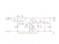
This is the shunt reg I was referring too on my last post. It’s actually identical to Justcallmedad with some other ideas which were discussed on that same thread and adjusted to give aprox. 24V.
Has not been tested yet but think it has great potential.
Has not been tested yet but think it has great potential.
Attachments
apassgear said:This is the shunt reg I was referring too on my last post. It’s actually identical to Justcallmedad with some other ideas which were discussed on that same thread and adjusted to give aprox. 24V.
Has not been tested yet but think it has great potential.
according to last 'xperiences from jh6you,when I urge him to try tl431,seems that zenner approach is maybe less noisier....but-try and tell us.....tnx to last playing with Babelfish and Oly's Mini,I didn't tested 431 in shunt reg,as I promised........
btw-nice job with PCB
Hi, mlloyd1,
First of all, I wanted to say that they way I use Jfet (in the noisiest area) could be very WRONG from the technical POV. I use it that way for myself, not suggesting others to do so
I've tried some other Jfets, like Electrocompaniet's K117, but to myself, the best sounding one is still 2SK30. Hiraga (or is it Kaneda?) uses 2SK30 about 0.25mA bias.
Maybe other JFET could be good in Q1's position, but I haven't tried very much type.
I want to write about my own (myself) experience. Something that I do not understand until now, is that why many "good" things in textbook do not result in the sonics that I wanted?
For example, there was time that I build cct's with very good regulators, cap multiplier etc. The sound is just "dead". Now I only use 1 R and 1 Cap forming pi-filter, and to me (myself) it sounds better than using complicated rail filter with many semiconductors. Again here I don't know why it is so to my ears. Using passive components (R-L-C) seems to sounds better to me than using semiconductors for rail filter (again : not for anyone's else's ear)
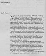
I make many cct's that will be blamed "wrong" from technical POV. I have books like DougSelf's kind of technical book, have built cct's based on those book's tutorial, but now I just make cct's based on 2 pages of Keith Jarret's Foreword in "Complete Guide to High End Audio" by Robert Harley. It helps me to convince myself when I'm making a "technically-wrong" audio cct's
I still haven't found what is the main guide in designing good sounding audio cct's. NP's recent cct's (ZenV9 with LU1014) makes me thinks harder now about what is tobe pursued
First of all, I wanted to say that they way I use Jfet (in the noisiest area) could be very WRONG from the technical POV. I use it that way for myself, not suggesting others to do so
I've tried some other Jfets, like Electrocompaniet's K117, but to myself, the best sounding one is still 2SK30. Hiraga (or is it Kaneda?) uses 2SK30 about 0.25mA bias.
Maybe other JFET could be good in Q1's position, but I haven't tried very much type.
I notice that majority of good sounding preamp seems to have quite low bias for the input transistor (like Q1 here), rather different than for power amps. Input transistor for preamp usually biased below 1mA, while for power amp usually above 1mA. I don't know this is only habit or there is technical reason why?Guess, as you say that the load for Q1 (R8) will make a lot of difference since we are changing operating parameters of the device.
Blowtorch thread? Yes that is very good thread.Due to Steen experiences I started following the Blowtorch thread with great interest, mainly on shunt PSU topics to see if I learned something “simple” that could be applied to this stage.
I want to write about my own (myself) experience. Something that I do not understand until now, is that why many "good" things in textbook do not result in the sonics that I wanted?
For example, there was time that I build cct's with very good regulators, cap multiplier etc. The sound is just "dead". Now I only use 1 R and 1 Cap forming pi-filter, and to me (myself) it sounds better than using complicated rail filter with many semiconductors. Again here I don't know why it is so to my ears. Using passive components (R-L-C) seems to sounds better to me than using semiconductors for rail filter (again : not for anyone's else's ear
)I make many cct's that will be blamed "wrong" from technical POV. I have books like DougSelf's kind of technical book, have built cct's based on those book's tutorial, but now I just make cct's based on 2 pages of Keith Jarret's Foreword in "Complete Guide to High End Audio" by Robert Harley. It helps me to convince myself when I'm making a "technically-wrong" audio cct's
I still haven't found what is the main guide in designing good sounding audio cct's. NP's recent cct's (ZenV9 with LU1014) makes me thinks harder now about what is tobe pursued
lumanauw said:
The sound is just "dead". Now I only use 1 R and 1 Cap forming pi-filter, and to me (myself) it sounds better than using complicated rail filter with many semiconductors.
Ah . . . you are a good student . . . got A+
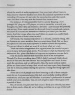
Question : what do you read in those 2 pages?
There are no "THD" or "S/N ratio" or "Damping factor" word in it. But for me it gives a clue what the "average ears" are looking for. ("average ears" here = everyone who don't design audio amplifiers or have soldering iron in their hands). If the music is sad, you have to be sad hearing the reproduction. If the music is happy, it has to make you happy hearing the reproduction. It's difficult to approach this, and strangely, this characteristic very often can be achieved with cct or approach that is said "wrong" in technical textbooks.
There are no "THD" or "S/N ratio" or "Damping factor" word in it. But for me it gives a clue what the "average ears" are looking for. ("average ears" here = everyone who don't design audio amplifiers or have soldering iron in their hands). If the music is sad, you have to be sad hearing the reproduction. If the music is happy, it has to make you happy hearing the reproduction. It's difficult to approach this, and strangely, this characteristic very often can be achieved with cct or approach that is said "wrong" in technical textbooks.
- Status
- This old topic is closed. If you want to reopen this topic, contact a moderator using the "Report Post" button.
- Home
- Amplifiers
- Pass Labs
- Threshold NS10 Lineamp PCB