The idea behind and only purpose of the prereg is to dispose any excessive voltage. An example could be if one wanted to install a buffer into an amp with 55V rails, then this is possible with the newly added preregulator. Another example is if one has a trafo with a too high secondary voltage, then this can be put to use , because of the prereg. The Toolereg alone would probably not be well, disposing eg 30V alone ") With a helping hand from the prereg, everything is fine. Flexibility.
With a helping hand from the prereg, everything is fine. Flexibility.
There is no real need for elaborating (making it more complicated) on the prereg. It is just meant as a handy tool in case of excessive voltage.
You will be perfectly fine, leaving it off alltogether, in most cases.
With a helping hand from the prereg, everything is fine. Flexibility.There is no real need for elaborating (making it more complicated) on the prereg. It is just meant as a handy tool in case of excessive voltage.
You will be perfectly fine, leaving it off alltogether, in most cases.
Hi Salas,
Good points you have there, This project has been a Universal sort of regulator so the raw supply has the ability to bypass the prereg and keep it the way it was as a CLC filter so nothing has been lost squeezing in the LM’s reg; this also allows anyone to use these supplies for a different purpose.
Still pending my 6V6 lineamp, hope to build it this coming month,
Cheers, Tony
Hi Tony,
I am set to experiment for the simplest possible no feedback high voltage ccs'ed shunt with easy to get components, for that 6V6. If it will work in practice, I hope that it will beat the Maida Mosfet 317 one that I use now. And it will be a universal HV PSU weapon if successful.
I am set to experiment for the simplest possible no feedback high voltage ccs'ed shunt with easy to get components, for that 6V6. If it will work in practice, I hope that it will beat the Maida Mosfet 317 one that I use now. And it will be a universal HV PSU weapon if successful.
Trafo for NS10
Somebody please
I planning to use this R-core trafo from diyclubbiz. It has 2 x 0-24V seccondaries and will feed through "raw supply" + Toolereg boards.
Is that OK?. Thanks for help
R-26-51 R-core
Somebody please
I planning to use this R-core trafo from diyclubbiz. It has 2 x 0-24V seccondaries and will feed through "raw supply" + Toolereg boards.
Is that OK?. Thanks for help
R-26-51 R-core
Re: Trafo for NS10
Yes, that will work fine. Nice trafo.
Manu, your boards arrived today, taking at least 1 day longer than usual, probably because of Christmas time.
JC Fardo said:Somebody please
I planning to use this R-core trafo from diyclubbiz. It has 2 x 0-24V seccondaries and will feed through "raw supply" + Toolereg boards.
Is that OK?. Thanks for help
R-26-51 R-core
Yes, that will work fine. Nice trafo.
Manu, your boards arrived today, taking at least 1 day longer than usual, probably because of Christmas time.
Manu said:Last version of the Raw supply (take #2)
Manu
Hi guys, excellent work
Cosmetic nit picking only....the traces between the diodes are not symetrical and they are different from each other (and the pads may not be in the centre of the trace ???). The extra pads for the filter cap would look better if they were both on Earth.
regards
Greg Erskine said:
Hi guys, excellent work
Cosmetic nit picking only....the traces between the diodes are not symetrical and they are different from each other (and the pads may not be in the centre of the trace ???). The extra pads for the filter cap would look better if they were both on Earth.
regards
Greg, thanks for pointing that out. I actually spotted the asymetri around the diodes, right away when I saw the board, that Manu send to me. Hadn't really noticed before. Lets see if there is more, when the boards are being built, so Manu can do a final "facelift" before sending any Gerbers out of the house
steenoe said:
so Manu can do a final "facelift" before sending any Gerbers out of the house
Certainly
Re: Resistors for toolereg
You are welcome. (Jacco said the same, just a little more cryptic)
I use a small local supplier, that carry Phillips 1% 0,6W E96 resistors. BC components took over Phillips's resistor manufactory plant (and other Phillips components) some years ago. I like the old green Phillips resistors, but the blue BC's are just as good. The supplier also carries the 1% axial foil polyprop's from Phillip's, which seems to have turned from blue to orange with BC at the steering wheel Those are the ones that I used for the Toolereg's 1nF and 10nF caps.
What resistor values are the problem? You can probably just use the nearest value available.
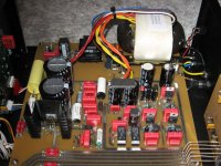
Edit. Come to think of it, Audio Research used something similar to the R-core trafo you linked to. Here is a pic of their LS17 preamp
JC Fardo said:Hello again
Thanks Steen for trafo advise.
What is your usual components supply. Mouser and Digikey seem to be short on some resistor values.
Later
You are welcome. (Jacco said the same, just a little more cryptic
) I use a small local supplier, that carry Phillips 1% 0,6W E96 resistors. BC components took over Phillips's resistor manufactory plant (and other Phillips components) some years ago. I like the old green Phillips resistors, but the blue BC's are just as good. The supplier also carries the 1% axial foil polyprop's from Phillip's, which seems to have turned from blue to orange with BC at the steering wheel
Those are the ones that I used for the Toolereg's 1nF and 10nF caps.What resistor values are the problem? You can probably just use the nearest value available.
Edit. Come to think of it, Audio Research used something similar to the R-core trafo you linked to. Here is a pic of their LS17 preamp
Attachments
Re: Re: Resistors for toolereg
Hi Steen. This is a previous BOM I´m trying to estimate for Toolereg so I may just be a little hurry. It´s exactlly those R4/R104 - 8.7K that set the voltage for NS10. Unless the PCB provides holes or tracks for a parallel array, it´s not a big deal
Thanks for your atention and support.
JC
steenoe said:
What resistor values are the problem? You can probably just use the nearest value available.
Edit. Come to think of it, Audio Research used something similar to the R-core trafo you linked to. Here is a pic of their LS17 preamp
Hi Steen. This is a previous BOM I´m trying to estimate for Toolereg so I may just be a little hurry. It´s exactlly those R4/R104 - 8.7K that set the voltage for NS10. Unless the PCB provides holes or tracks for a parallel array, it´s not a big deal
Thanks for your atention and support.
JC
I have a few questions... how flexible is that 400 ohm value? 390-420 okay? same with 90 ohm.
Also, I've been hunting through this thread to find diameter, lead spacings, and what not for the shunt and the prereg boards, but haven't found anything nice and compact. It should only be a few parts here and there, does anyone happen to have this info?
Finally, I have a use for these boards that is a low current draw, around 4-10mA. In this case, is there a guideline on how much the CCS should draw, and perhaps a formula on how to compute R6/R106 instead of a table? With a lower CCS value / overall current draw, can I get away with a 0.5W resistor here?
Thanks everyone!
You could easily use other values for R1 like the values you mention as well as R11 you can use 100 Ohms there with no detrimental effect. Most values shown on the schematics are a result of best fit on sims.
Lead space for all 1/4W resistors on the original layout is 0.360” and for R6 1W is 0.555” thou the Gerber files might be a bit different.
We showed some guidelines on the Hints for setting the regs, but generally speaking the more current you burn on the shunt transistor the better performance but of course this has limitations on heatsinking and raw supply capacity, this doesn’t mean you should go overboard. For low loads you may want to set the CCS at something like 60 or 80mA, but feel free to experiment other settings.
To be on the safe side you need a 1W resistor for R6, if you cant get resistors on that rating I would suggest you parallel (piggyback) a couple of 1/2W resistor of similar value leaving some space between both and the board for better air circulation.
Cheers
Predator864 said:What is the output voltage range (min and MAX ) for the shunt regulator ?
There is a reissue of the Hints pdf in the GB thread that gives a fair explanation.
So far, with this topology it has been tested from 15 to 30V. In the other hand if you read the last pages of this thread you will find Colin posts suggesting lower voltage mods.
Re: Re: Re: Resistors for toolereg
R4/R104 does not need to be excact value. R15/R115 is on the GB boards changed to a trimpot that gives you a fairly large adjustment range. Just pick something pretty close and you will be fine.
JC Fardo said:
Hi Steen. This is a previous BOM I´m trying to estimate for Toolereg so I may just be a little hurry. It´s exactlly those R4/R104 - 8.7K that set the voltage for NS10. Unless the PCB provides holes or tracks for a parallel array, it´s not a big deal
Thanks for your atention and support.
JC
R4/R104 does not need to be excact value. R15/R115 is on the GB boards changed to a trimpot that gives you a fairly large adjustment range. Just pick something pretty close and you will be fine.
For those interested on the NS10 lineamp let me tell you that we already have a quote for PCB’s as described on this thread.
http://www.diyaudio.com/forums/showthread.php?s=&postid=1694962#post1694962
If your are interested on building this classic preamp just show your interest on this Wiki
http://www.diyaudio.com/wiki/index.php?page=Toole+Regulator+PCB+GB+
Cheers,


http://www.diyaudio.com/forums/showthread.php?s=&postid=1694962#post1694962
If your are interested on building this classic preamp just show your interest on this Wiki
http://www.diyaudio.com/wiki/index.php?page=Toole+Regulator+PCB+GB+
Cheers,
- Status
- This old topic is closed. If you want to reopen this topic, contact a moderator using the "Report Post" button.
- Home
- Amplifiers
- Pass Labs
- Threshold NS10 Lineamp PCB