Perfection is the enemy of good - or something like that.
I agree with ZenMod.
I have an extraordinarily simple build of the NS10, and have had it running for 5 - 8 years, made with boring parts except for a JFET for Q1, and it is not the weakest part of my DIY system. (My first ever, home design LM3886 chip amps are the worst bit - I have lots of digital noise being picked up from the environment and my Mac computer somehow. And a bit of hum. None of this is from my NS10 Clone. Thanks to Mr. Pass for this design.)
Let your space constraints (in the case), time restraints and budgetary restraints guide you. And just build the thing. The circuit is very forgiving.
Regards,
George.
Last edited:
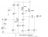
which version do you use and which one sounds better? i have found 4 versions and i dont know which one to choose. i opt for the basic version the simplest one with no opamp but what about the 5p feedback cap?or the current source instead of the 2k7 resistor? i dont know which one of all this versions sounds better so if someone has impressions for each version it would be very helpful.i am looking for warm tubish sound.
Attachments
Last edited:
The version I built
Copied from my defunct webpage:
This preamp appealed to me because it could be built very cheaply and very quickly to fulfil my need for a pre-amplifier. It was urgent in fact, because I had just finished my chip power amps, realized I had no pre-amp and wanted to try out my all new Linkwitz Orion- based hifi that weekend!
Of course what I built was nothing comparable to what Passlabs would have built. Mine was built with a bunch of el cheapo parts I got at the local Jaycar, a superquick PCB I knocked up and etched myself. The transistors cost about 20 cents each.
I used BC series transistors initially (20 to 50 cents a pop at Jaycar) and later then changed Q1 for a Jfet (SK30 if I recall correctly) which I bought from a mail order electronics mob in Thailand. The jfets sounded different, and probably better, but they are certainly not compulsory.
There are lots of posts, some meaningful, some not, about the choice of transistors for this circuit, as there always in the DIY world. I honestly cannot remember what is in this circuit at present for Q2 and Q3!!
The power supply is a bog standard chip-based thing, (in an external, wooden box behind my stereo cabinet, a big EI transformer, bog standard rectifier bridge, an embarrassing capacitance 20 000 uF or more per rail using an old capacitor bank I had from my first chip amp project: unregulated power running to the 1U case in the picture, adjustable voltage regulator in the 1U case (because Rod Elliott reckons that the fixed voltage LM regulators are "just noise generators").
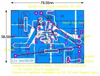
Similarly, there are lots of capacitor options side by side on the circuit board because I like to be able to "bypass" the electrolytics and other large value capacitors with small value polypropylene capacitors. Unfortunately, small value polypropylene capacitors tend to be big bulky things so they take more space than you might imagine. (C1,C5,C8 is the bank of capacitor options for the input signal; C2a,b,c are the output capacitors, C3 is a grounding thing which I don't understand but it looks like it should be bypassed, and C6 and C7 are the capacitors for filtering the power supply. You see what I mean: you can spend hours reading the internet about bypassing capacitors, and really it becomes very much like a cookery lesson! "What do I have? Mmmm, that tastes/sounds nice.")
I am still very statisfied with this pre-amp. It is very quiet and clean.The total cost of assembling this circuit WITH transformer and case was initially about $80-90AUD, which is essentially NOTHING! The new jfets cost about $9AUD each so the whole thing still cost nearly nothing.
I have used this pre-amp since 2006 so it represents superb value!
Finally, do not overanalyze too much of this. (Same advice as I gave in the above post") )
)
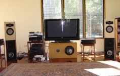
Sometimes it is just best to start building as I did with this project. You can see it as the 1U box with the scrap aluminium front - partially open! - in my stereo stack to the left of the TV!
>>"I am looking for a warm, tubey sound">>
With a low noise BJT as Q1 you get a warmer, more laid back sound than with the JFET as Q1. Just "roll" those transistors to have fun choosing your sound.
(I used to think I liked "warm, tubey" sounds, but no more. I can't hear the 16kHz on Sgt. Pepper any more, so I desire more detail perhaps, but on the other hand, the better the solid state amp and the better the tube amp, the more they start to sound similar I think. )
)
Copied from my defunct webpage:
This preamp appealed to me because it could be built very cheaply and very quickly to fulfil my need for a pre-amplifier. It was urgent in fact, because I had just finished my chip power amps, realized I had no pre-amp and wanted to try out my all new Linkwitz Orion- based hifi that weekend!
Of course what I built was nothing comparable to what Passlabs would have built. Mine was built with a bunch of el cheapo parts I got at the local Jaycar, a superquick PCB I knocked up and etched myself. The transistors cost about 20 cents each.
I used BC series transistors initially (20 to 50 cents a pop at Jaycar) and later then changed Q1 for a Jfet (SK30 if I recall correctly) which I bought from a mail order electronics mob in Thailand. The jfets sounded different, and probably better, but they are certainly not compulsory.
There are lots of posts, some meaningful, some not, about the choice of transistors for this circuit, as there always in the DIY world. I honestly cannot remember what is in this circuit at present for Q2 and Q3!!
The power supply is a bog standard chip-based thing, (in an external, wooden box behind my stereo cabinet, a big EI transformer, bog standard rectifier bridge, an embarrassing capacitance 20 000 uF or more per rail using an old capacitor bank I had from my first chip amp project: unregulated power running to the 1U case in the picture, adjustable voltage regulator in the 1U case (because Rod Elliott reckons that the fixed voltage LM regulators are "just noise generators").
Similarly, there are lots of capacitor options side by side on the circuit board because I like to be able to "bypass" the electrolytics and other large value capacitors with small value polypropylene capacitors. Unfortunately, small value polypropylene capacitors tend to be big bulky things so they take more space than you might imagine. (C1,C5,C8 is the bank of capacitor options for the input signal; C2a,b,c are the output capacitors, C3 is a grounding thing which I don't understand but it looks like it should be bypassed, and C6 and C7 are the capacitors for filtering the power supply. You see what I mean: you can spend hours reading the internet about bypassing capacitors, and really it becomes very much like a cookery lesson! "What do I have? Mmmm, that tastes/sounds nice.")
I am still very statisfied with this pre-amp. It is very quiet and clean.The total cost of assembling this circuit WITH transformer and case was initially about $80-90AUD, which is essentially NOTHING! The new jfets cost about $9AUD each so the whole thing still cost nearly nothing.
I have used this pre-amp since 2006 so it represents superb value!
Finally, do not overanalyze too much of this. (Same advice as I gave in the above post
)Sometimes it is just best to start building as I did with this project. You can see it as the 1U box with the scrap aluminium front - partially open! - in my stereo stack to the left of the TV!
>>"I am looking for a warm, tubey sound">>
With a low noise BJT as Q1 you get a warmer, more laid back sound than with the JFET as Q1. Just "roll" those transistors to have fun choosing your sound.
(I used to think I liked "warm, tubey" sounds, but no more. I can't hear the 16kHz on Sgt. Pepper any more, so I desire more detail perhaps
, but on the other hand, the better the solid state amp and the better the tube amp, the more they start to sound similar I think.)Attachments
Last edited:
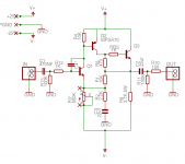
Hello.I am building the NS10 preamp based on this schematic.
For MPS6571 i am gona use MPSA18 as suggested but what should i use in place of 2N4250?
I have bC550C-560C,2N5401-5551,2SC2240-2SA970.
If i want to have lower gain can i use 680ohm feedback resistor instead of 301ohm?
What about the 1K resistor between 2N4250 collector and MPS6571 base shown on some other schematics?Should i use this resistor or not?
Attachments
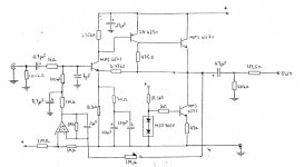
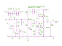
I also used MPSA18 for the NPNs and BC560C for the PNPs.I also used 680ohm feedback resistor instead of 301ohm and 1K resistor between 2N4250 collector and MPS6571 base and a dual opamp LF353 for both channels. It sounds detailed,analytical,accurate as you stated earlier.
MPSA18 were bought from tayda electronics.My worry is whether they are genuine or not and if should i use BC550C instead of the MPSA18 i got from Tayda Electronics.
This is the schematic i used:
MPSA18 were bought from tayda electronics.My worry is whether they are genuine or not and if should i use BC550C instead of the MPSA18 i got from Tayda Electronics.
This is the schematic i used:
Attachments

Last edited:
- Status
- This old topic is closed. If you want to reopen this topic, contact a moderator using the "Report Post" button.
- Home
- Amplifiers
- Pass Labs
- Threshold NS10 Lineamp PCB