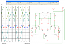
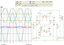
I made the correction on my latest schematic layout. Cool, it raised the sine-wave upwards on the volt scale--should allow for a bit more input voltage without clipping the lower half of the sine-wave.
It's difficult for me to locate a large dual five volt supply, so I'm toying with a ten volt power supply with the additon of a virtual ground. I hope that someone will be kind enough to explain whether or not my attempt has merit.
Many thanks, guys.
John
It's difficult for me to locate a large dual five volt supply, so I'm toying with a ten volt power supply with the additon of a virtual ground. I hope that someone will be kind enough to explain whether or not my attempt has merit.
Many thanks, guys.
John
Attachments
Zen Mod said:
even better - use CCS as Papa like it - mosfet + little bjt
Hey Choky, how's this?
Attachments
carpenter said:
Hey Choky, how's this?
wrong ;
you are loosing advantages of linearisation when CCS is in tail , complicating with series CCS-es and chokes
Zen Mod said:
wrong ;
you are loosing advantages of linearisation when CCS is in tail , complicating with series CCS-es and chokes
back to the drawing board for me........
")
Thanks, Choky!
carpenter said:This seems to work, and if a bit more efficient:
finding 6V xformers ( even SMPS ) isn't so hard , so it's easy to make +/- 6V PSU;
keep gates on gnd potential , common CCS on - 6 and chokes at +6
Zen Mod said:
finding 6V xformers ( even SMPS ) isn't so hard , so it's easy to make +/- 6V PSU;
keep gates on gnd potential , common CCS on - 6 and chokes at +6
To be quite honest, I'm trying to play with the parts in my junk drawer. Money's a little bit tight at the moment. I was hoping that my virtual ground idea would save me a couple of bucks. But, if you think that dual transformers are the way to go, I'll put more effort into finding a pair.
John
carpenter said:
To be quite honest, I'm trying to play with the parts in my junk drawer. Money's a little bit tight at the moment. I was hoping that my virtual ground idea would save me a couple of bucks. But, if you think that dual transformers are the way to go, I'll put more effort into finding a pair.
John
make a sim or few with these voltages and observe
then decide ;
nobody is smarter than you , for your wallet
carpenter said:Thanks for the advice, Choky.
naah ....
you're big boy ( with big horns
)you already knew that
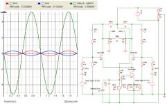
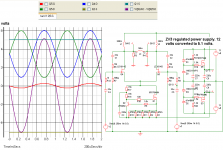
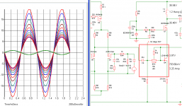
Now, this is fun. I simmed Nelson's ZV3 regulated power supply and attached it to my latest creation. Wonder of wonders, it works!
What blows me away about this process is that the voltage swing is rail to rail--at least the sim thinks it is. Now I can put my transformers to work!
What blows me away about this process is that the voltage swing is rail to rail--at least the sim thinks it is. Now I can put my transformers to work!
Attachments
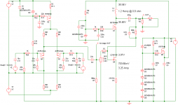
I split the ZV7-T (with cascode) down the middle and added what I think could be called a balanced-in-to-single-ended-out buffer. It also has Nelson's voltage regulator. So, I guess it more resembles a ZV9. Performance looks good on the simulator. The best part? Being single ended, it's easier to build.
My electronic x-over has balanced outputs--hence the desire to employ a balanced to single-ended converter.
My electronic x-over has balanced outputs--hence the desire to employ a balanced to single-ended converter.
Attachments
carpenter said:I split the ZV7-T (with cascode) down the middle and added what I think could be called a balanced-in-to-single-ended-out buffer. It also has Nelson's voltage regulator. So, I guess it more resembles a ZV9. Performance looks good on the simulator. The best part? Being single ended, it's easier to build.
My electronic x-over has balanced outputs--hence the desire to employ a balanced to single-ended converter.
why caps everywhere ?
at least C6 , C11 ,C12 , C13
and- that output load choke must be substantial ...... considering massive Iq ( it isn't split load choke , where yo have flux cancellation )
Zen Mod said:
why caps everywhere ?
at least C6 , C11 ,C12 , C13
and- that output load choke must be substantial ...... considering massive Iq ( it isn't split load choke , where yo have flux cancellation )
Thanks for looking. I'll sim without the caps you mentioned. Again, thanks.
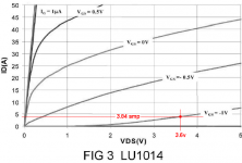
The power in the inductor is 16 watts RMS according to the simulator. The tranny I have on hand is rated at 1000 watts. I figured that the core may be large enough to tolerate the inductance without saturating. I haven't learned how to create a full-blown inductor in my simulator, yet.
Your thoughts are much appreciated, Choky.
Zen Mod said:
why caps everywhere ?
at least C6 , C11 ,C12 , C13
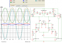
I removed those four caps and everything is looking good; in fact, the sine wave looks exactly the same on the simulator. Thanks a bunch for the education.
- Status
- This old topic is closed. If you want to reopen this topic, contact a moderator using the "Report Post" button.
- Home
- Amplifiers
- Pass Labs
- ZV7-T (transformer)