I just start the artwork for the pcb on the Babelfish J with input SJ109BL (because I have some).
I also have a lot of 0.47 Ohm/5W resistors. Would there be an easy way to calculate the needed R- value with a given voltage and Iq and so the output wattage or other way around?
Or in other words: I like to use these resitors and my max. power should be 25-30 W, so which voltage and Iq I have choose?
you're going to use IRFP150?
meaning - one output pair ?
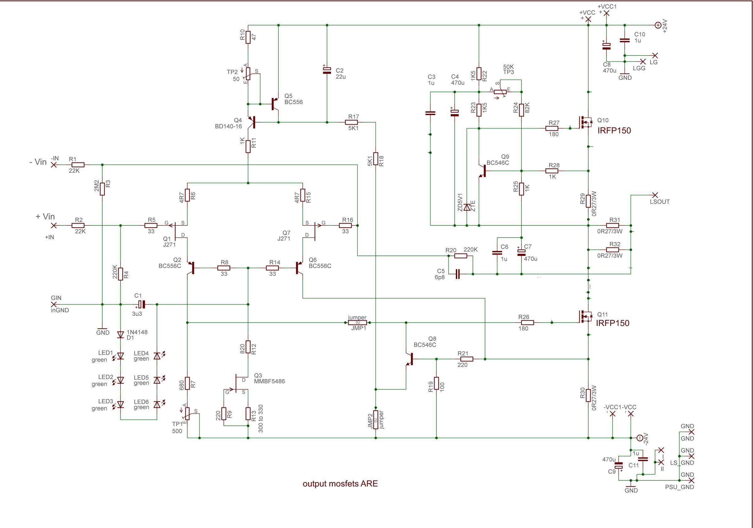
Jap, I´m using the IRFP150, and your schematic from http://www.diyaudio.rs/choky/Babelfish J.html....
35 years ago when I built my first amp I learned, that for an "acusticly" good room you only need about 1 W per sqm. How true. So this time also I do not want to build an overkill either. Small case, less heat, a nice little package.
And I like to use the parts I allready have.
35 years ago when I built my first amp I learned, that for an "acusticly" good room you only need about 1 W per sqm. How true. So this time also I do not want to build an overkill either. Small case, less heat, a nice little package.
And I like to use the parts I allready have.
feel free to use your fave 0R47 as biggie resistors , if you are satisfied with Iq up to 0V65/0R47=1A38
stay with regular FW PSU - based on 2 x 18Vac secondaries ( F4 manual at FW , for instance , is having nicely drawn one) , resulting in approx. 22.5Vdc rails
if you want more than 1A38 per IRFP150 vertical pair , then just double (parallel) your 0R47 resistors in all positions (both source and sense resistors , in short - all 0R27 drawn here )
I believe then you'll be able to set precise Iq with trimpot , trowing no more than 50W of heat through each ..... and that would be around 2A for Iq
under condition that htsnks (mosfets through mica and white drek , or better) are in comfort zone - up to 55C in summer time
if needed , make Babysitter
Attachments
Last edited:
Well Zenmod, that´s the answer I was looking for. Thanks.
So with 22,5 V and 1,38 A I get 31,05 Watts trough des IRFP150, with 0,27 Ohms its 2,4 A, resulting in 54,2 Watts.
Understood (hopefully)....
What is the purpose of R22/R23 in this diagram, would be my last question.
So with 22,5 V and 1,38 A I get 31,05 Watts trough des IRFP150, with 0,27 Ohms its 2,4 A, resulting in 54,2 Watts.
Understood (hopefully)....
What is the purpose of R22/R23 in this diagram, would be my last question.
I just bought some IRFP150's. I also have a bunch of the nice light blue Panasonic 0.47R 3W resistors and was wondering the same thing about using them. Seems Ok. I can definitely handle 60W on my heatsinks and probably even a bit more as they were not that warm at 60W.
What is advantage of 150's over 240's?
The above schematic is very different than this one which the board I have from this thread:
What is advantage of 150's over 240's?
The above schematic is very different than this one which the board I have from this thread:
Last edited:

everything pretty much explained in Aleph CCS patent - entire series of amps got name from that
lower mosfet is commanded by input LTP , directly amplifying input signal , then current goes to ldspk through small resistance ( biggies connected in parallel) , then voltage sag across them is directly used (through C7 and C6 and R25 ) to modulate Aleph CCS
what is nice and clever there ...... modulation of Aleph CCS is pretty much dependable of nature of load ...... I mean loaaaaaadspeeker
patent ; go here and paste this number : 5710522
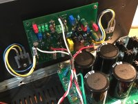
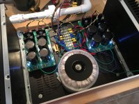
PSU with 400VA trafo and dual Prasi/Project16 CRC Class A PSU's finished and working. 1mV ripple with zero load:
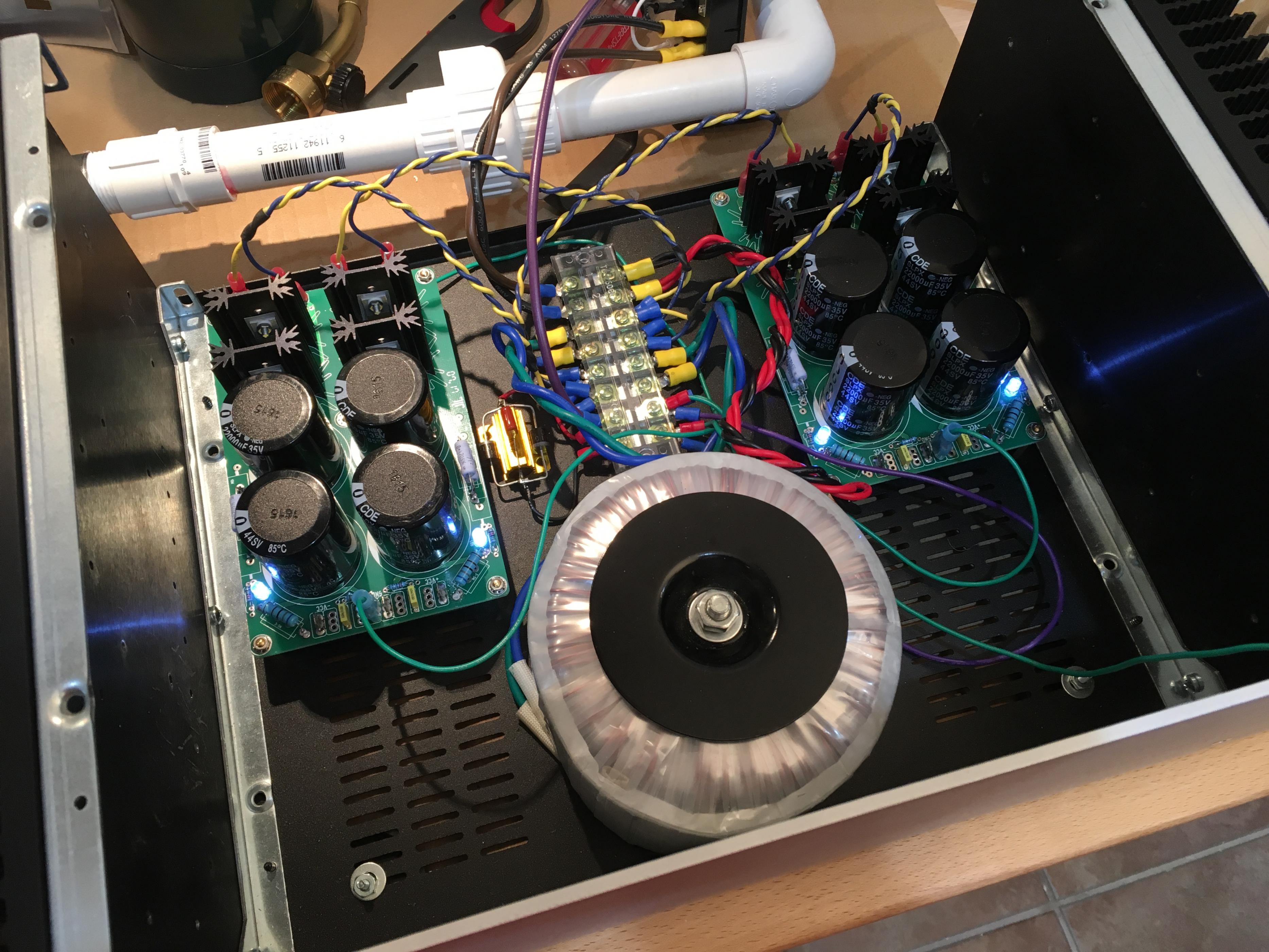
The Babelfish J PCB has screw holes that fit DIYA UMS heatsink (3 screws perfect). However, MOSFETs have to be flying leads and offboard. Getting closer:
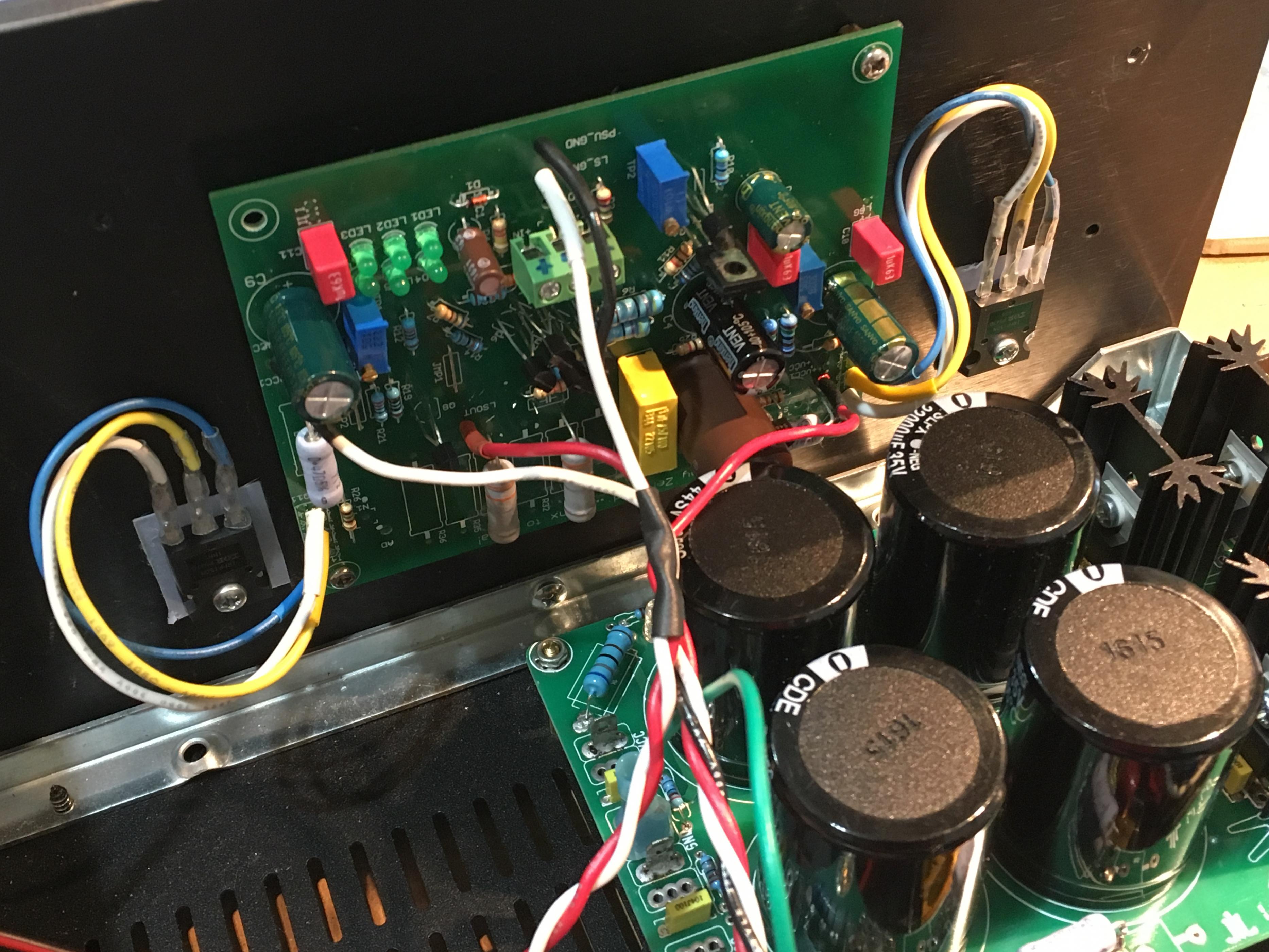
C5 is now made by putting qnty 3 x 22pF NP0 0805 caps in series and soldered directly to bottom side between two pins. 7.3pF should be close enough. I guess the voltage rating actually goes up 3x with caps in series?
The Babelfish J PCB has screw holes that fit DIYA UMS heatsink (3 screws perfect). However, MOSFETs have to be flying leads and offboard. Getting closer:
C5 is now made by putting qnty 3 x 22pF NP0 0805 caps in series and soldered directly to bottom side between two pins. 7.3pF should be close enough. I guess the voltage rating actually goes up 3x with caps in series?
Attachments
Last edited:
completely other thread ")
better to go there - ( in fact , you've been there ) : About possible Babelfish J interest
let me know do you need more info ..... forgot what's written
better to go there - ( in fact , you've been there ) : About possible Babelfish J interest
let me know do you need more info ..... forgot what's written
- Status
- This old topic is closed. If you want to reopen this topic, contact a moderator using the "Report Post" button.
- Home
- Amplifiers
- Pass Labs
- Babbelfish J PCBs