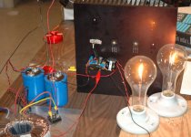
Well, i finished wiring up the circuit today on the test bench.
Apon turning it on the first time - the light bulbs didn't come on.
I immeadiately adjusted P1 by turning it all the way clockwise. I
always seem to wire up pots backwards.
(one day i'll learn how to wire a pot?)
After a slight delay the light bulbs lit. Input voltage was at 55 volts.
I was getting good readings at all the test points - just slightly higher,
due to the extra voltage my PSU putting out.
The problem is i was getting 0 volts at the output.
Well, i figured this was because i had the pot at minnimum value.
So slowly, very slowly! i just touched the pot up a fraction, and the
light bulbs went out. I was measuring voltage at the output now
and all other values were very high. Setting P1 back to minimum
value did nothing. Needless to say i turned off the amp right away.
I suppose i need to re install P1 correctly for starters... any other ideas?
Thanks for any help.
m.
Moe29, having a little fun are we? First, I think you should have 0V at the output with no signal. But the Drain of Q2 should have 25V plus or minus, and at that point the lights should be lighting. On that basis, I would use a volt/ohm meter and make sure the P1 is the value you think, 25k? You want the adjusted value to be low at power-up so the Q1 is in a safe condition(low voltageD-S) And then power it up and monitor the voltage at the gate of Q2. You probably want about 8.5V plus or minus when adjusted and that should get you the 25V at the Drain of Q2. Much more than 9-10V at the gate of Q2 and I would shut down imediately and go over the circuit visually again... I'l be doing this myself in a few days, Good Luck...
I replaced P1 and connected it properly.
The circuit is back up and running.
Mr. Pass isn't kidding when he says to SLOWLY, very slowly adjust the
value of P1") I'm using the Bournes part that shows up in other
I'm using the Bournes part that shows up in other
Pass DIY projects. It's a 1 turn piece (3386P-253-ND, Digikey#)
I noticed that if you adjust to fast, the light bulbs go out!
Here's a few measurements with P1 at it's minimal value.
55.7 volts IN
4.92 V on the drain of Q1
1.42 V on the source of Q1
9.21 V at the point near R5
4.30 Vgs on Q2
1.39 Vgs on Q1
23.89 V on the Drain of Q2
17mV at the Output
So now i suppose i have to make adjustments until i get 25V on the
output. Should there be a load on the circuit when you do this?
My transformer is giving me 55.7 volts. It's 650VA with 40 volt secondaries. I'm using a CLC PSU 68,000 uF - 2mH - 68,000 uF.
I suppose i should have purchased a transformer with 35 V secondaries.
I'll probably finish working on this tomorrow when i have more time.
The circuit is back up and running.
Mr. Pass isn't kidding when he says to SLOWLY, very slowly adjust the
value of P1
I'm using the Bournes part that shows up in otherPass DIY projects. It's a 1 turn piece (3386P-253-ND, Digikey#)
I noticed that if you adjust to fast, the light bulbs go out!
Here's a few measurements with P1 at it's minimal value.
55.7 volts IN
4.92 V on the drain of Q1
1.42 V on the source of Q1
9.21 V at the point near R5
4.30 Vgs on Q2
1.39 Vgs on Q1
23.89 V on the Drain of Q2
17mV at the Output
So now i suppose i have to make adjustments until i get 25V on the
output. Should there be a load on the circuit when you do this?
My transformer is giving me 55.7 volts. It's 650VA with 40 volt secondaries. I'm using a CLC PSU 68,000 uF - 2mH - 68,000 uF.
I suppose i should have purchased a transformer with 35 V secondaries.
I'll probably finish working on this tomorrow when i have more time.
Hmmm....
Something else must be wrong becuase i was just trying to adjust the
circuit again - and it failed.
I was just barely moving P1 and the bulbs went out again...
After the lights went out i was getting 23V at the output.
I didn't do any other measurements as i turned the amp off right away.
I did double check P1s value before reinstalling.
Seems strage that i would get good reading and things seem stable
at the minimum value of P1. I let it run that way for about 30 minutes
and the heatsink just got warm - so nothing was getting hot at all.
i must be overlooking something... will check it out again tomorrow.
Hey Moe29, very cool, congrats and all. I forgot to mention when you get near the threshold of Q2 things change quick. A one turn pot would change very quick. I usually use something like a 10-20 turn in an adj like that. And, I also will use another resistor in series to take most of the power and a smaller pot so there is a smaller adjustment range. You have to guess a little better what you need though...
If I may point out a few things I noticed imediately you might think about. You say you have 1.42V on your source resistor, that means you have 2.86A. Wasn't the original design set up for 2Amps??? That might be the Vds of Q1 being a few tenths higher than N.P. suggested??? It may be the actuall value of your Rsource is smaller than the stated value? Measure it (hot). I'm not sure. You can lower the cascode ref votage(P1) a little to 9V and it may drop to the 2A area???
No about the load. Any load is on the other side of the output cap. The only DC out there should be the JFET gate current that is causing that 17mV.
The 25V bis should only be a suggestion, especially in your case. What I ussually do is take a critical pk-pk votage measurement on a scope of the output swing cranked all the way to clipping. I would adjust the Drain of Q2 so that clipping occurs in both halves of the waveform at about the same time as I am raising the input signal level...

Well P1 was toasted again... i just checked it.
Can you reccomend a part number for a multi-turn pot?
I think the circuit is assembled correctly, it's just the pot is to coarse.
I'm out of pots... so i'll have to wait until i get an order in.
FLG, thanks for the comments and ideas
Can you reccomend a part number for a multi-turn pot?
I think the circuit is assembled correctly, it's just the pot is to coarse.
I'm out of pots... so i'll have to wait until i get an order in.
FLG, thanks for the comments and ideas
O.K. I have these 10K deals I got from Mouser. I laid out my board for them. They are Bourns 3/8 inch square and sealed. The bag says mfg part #3296P-1-103. The Mouser # is 652-3296P-1-103. You should be able to find a 25k that is almost the same. Try changing the 103 to 253
If this pots burning up that does not sound like the I thru it is correct or something. I'm not actually looking at the circuit but I'll bet N.P. doesn't have more than a mA or so thru it.... I havent even thought about how to check one of these litte JFETs yet... Hmmm 2 diodes back to back??? Sounds like another device we know???
At least from your data, you are very close to a working circuit... Are you the first one??? I'm not sure I've actually read about a completed prototype other than "the one and only" have I?
Your very welcome. glad to help if I can...
...i was wiring P1 incorrectly.
maybe one day i'll learn to wire a potentiometer correctly.
right now i'm trying to get the circuit dialed in.
I'll post an update when i get the other channel built and the thing
in some kind of chassis. I'm curious to give it a listen and compare it
to my Zen amp. (version 1 with PSU updates)
maybe one day i'll learn to wire a potentiometer correctly.
right now i'm trying to get the circuit dialed in.
I'll post an update when i get the other channel built and the thing
in some kind of chassis. I'm curious to give it a listen and compare it
to my Zen amp. (version 1 with PSU updates)
Moe, not all trimpots acts the same. I usually put my Multimeter on the pins to see excactly how a particular pot behave's. Just for safety measuresi was wiring P1 incorrectly.
Steen
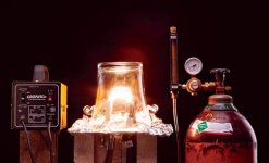
DIY light bulbs
i thought i'd revive this thread instead of making a new one...
i found this interesting article.... In order to make a truly DIY Zen V8
i think a DIY lightbulb is in order!
How to DIY a lightbulb
...if i could ever get around to making a chasis for my Zen V8 i could
finish it. maybe i'll just finish it sans-chasis and give it a listen!
i thought i'd revive this thread instead of making a new one...
i found this interesting article....
In order to make a truly DIY Zen V8i think a DIY lightbulb is in order!
How to DIY a lightbulb
...if i could ever get around to making a chasis for my Zen V8 i could
finish it. maybe i'll just finish it sans-chasis and give it a listen!
Attachments
- Status
- This old topic is closed. If you want to reopen this topic, contact a moderator using the "Report Post" button.
- Home
- Amplifiers
- Pass Labs
- Zen V8 Troubleshooting