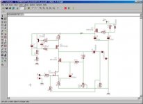
I fiddled around with Eagle to try and make a working ZenV8 with CCS and capacitance multiplier/regulated supply. I have used the CCS from the F2 clone and the familiar Zen regulated supply without the zeners. Since my "mentor" Apassgear is travelling around in south-america right now, I would like to have your comments on the circuit, please. I adjusted the railvoltage in the "normal" Zen fashion. Any corrections would be greatly apprieciated") I used the P-channel device for the CCS because I have a tube of those, sitting around.
I used the P-channel device for the CCS because I have a tube of those, sitting around.
Steen
I used the P-channel device for the CCS because I have a tube of those, sitting around. Steen
Attachments
Hi,
correct me if I'm wrong, but you are using a MOSFET in the your regulator and not a BJT .. so this is not a real capacitance multiplier.. you may need a resistor to ground from the gate of the MOSFET to set a DC-point. The MOSFET draws no gate current, like a BJT draws a base-current, so there's no voltage drop around the gate resistors in your circuit.....
correct me if I'm wrong, but you are using a MOSFET in the your regulator and not a BJT .. so this is not a real capacitance multiplier.. you may need a resistor to ground from the gate of the MOSFET to set a DC-point. The MOSFET draws no gate current, like a BJT draws a base-current, so there's no voltage drop around the gate resistors in your circuit.....
I’m back Steen, nice to see that you are all out designing some amps now!!! Nice work.
I’m more a hands on when it comes to design something (simple of course) so I’m not much of a help when it comes to theory on a schematic form and I have little experience on cascoding and biasing a jfet, but as you know there are many guys around this forum that are quite capable and will show up with some hints to make a workable amp. Even though we do have ZV8 schema as a reference.
Looks to me that you may need a ground reference to the gate of Q1 just before R1 even though R11 may do to that reference.
If you find oscillations on the circuit you may try moving R10 to the left just prior to the gate of Q5 which will work as a grid stopper, same as Fig 10 on ZV8.
Thanks a lot for the replies Wellcome home Tony Hope you had a nice trip I will take a look at the things you and Tschrama mentioned Well, I dont know much about designing, to say the least I would just like to build an amp like the schematic posted I know NP will put the ZV9 up on PassDIY next week, but I would like to try this one, too So just let me know if there is more?
Steen
Wellcome home Tony Hope you had a nice trip I will take a look at the things you and Tschrama mentioned Well, I dont know much about designing, to say the least I would just like to build an amp like the schematic posted I know NP will put the ZV9 up on PassDIY next week, but I would like to try this one, too So just let me know if there is more?Steen
steen's multiplier is replicated from Z V3
here is what Papa sez:
"The circuit does not actually require the use of Zener diodes to
work well for many purposes. If you take the Zener diodes out,
then the circuit simply filters out the AC voltage from the supply
value, leaving the DC value and giving a DC output voltage about
4 Volts less than the unregulated voltage. I prefer the value
stability with the Zeners in, as they represent only a small
investment in parts."
'nuff from me for now
You made my day, NelsonI'm sure you will be very amused to see ZV9 next week.
Thanks a lot Just what I was thinking when I draw'ed up the schematichere is what Papa sez:
Steen
steenoe said:You made my day, Nelson
Just what I was thinking when I draw'ed up the schematic
Steen

just little correction in your circ-moved one leg of cap in cascode
regarding ground refference for gate of Jfet- R2 and R11 are in same time part of NFB loop and gnd reference for gate
think toobie
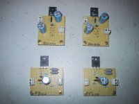
ole sheeeeeeeet with toobz
Attachments
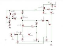
steenoe said:That is correct. R2 does not connect to the ground line. It connects only on top of R11. My sch doesnt make that clear
Please keep looking Choky, I want to get all faults corrected
Steen
your schmtc make that clear good enough
what I want to say-contrary ro our mate apass-you have perfectly good ground return for gate : R2+ R11 =47K5+1K
gate is referenced to gnd
current through R12 results in voltage for Jfet biasing
same as with triode (now even choky can understand that bloody SS language
)Hey Choky and Steen,
All said on my post if you read my lips. As I was writing realized that R11 could also serve as grd reference that’s why I added the last part on the sentence.
Same thing with R10, after writing I had a look at the ZV8 circuit and added Fig 10 as reference 
All said on my post if you read my lips. As I was writing realized that R11 could also serve as grd reference that’s why I added the last part on the sentence.
Same thing with R10, after writing I had a look at the ZV8 circuit and added Fig 10 as reference
apassgear said:Hey Choky and Steen,
All said on my post if you read my lips. As I was writing realized that R11 could also serve as grd reference that’s why I added the last part on the sentence.
Same thing with R10, after writing I had a look at the ZV8 circuit and added Fig 10 as reference
just teasin'.......
ya know that steen is sometimes in a hurry
ya must tell him twice some things..........

besides-forum communication-slow and echoed
sometimes like "broken phones"
hey- how Babbelfish look to ya?
Yep you got that rightya know that steen is sometimes in a hurry
Your Babbelfish just look great!! Hmmm, yes something has to be told twice allright I dont mean to have broken phones with: Choky and Apassgear Steen
Sorry .. but I still don't get how this cap-multiplier can work?
There's no DC current flowing in the resistors and diode associated with Q3 .. how can Q3 reach a proper bias setting?
Did 'papa' call it a cap-multiplier? shouldn't it be called a technics virtual battery arangment or something like that?
There's no DC current flowing in the resistors and diode associated with Q3 .. how can Q3 reach a proper bias setting?
Did 'papa' call it a cap-multiplier? shouldn't it be called a technics virtual battery arangment or something like that?
choky said:
hey- how Babbelfish look to ya?
That fishy thing looks really nice, congrats!!! Hope to do it someday.
Choky no longer can hide under the toobs… welcomed to the dunes!!!
tschrama said:Sorry .. but I still don't get how this cap-multiplier can work?
There's no DC current flowing in the resistors and diode associated with Q3 .. how can Q3 reach a proper bias setting?
Did 'papa' call it a cap-multiplier? shouldn't it be called a technics virtual battery arangment or something like that?
Q3's gate is referenced to ground (via 22oUF cap at gate) only when AC (noise,ripple) came in ;in a meantime Q3 just sits there,eating approx. 4 V of PS voltage
diode is there just for protection
at least this is how I understand this
steenoe said:Hey Tony, how was your trip to the south?? We missed you a lot around here!!
Steen
Thanks Steen, nice words.
Spent some days with my 90 years old good mother in sunny Viña del Mar, wonderful vacations. Also had the chance to see the Queen Marry II sail from port.
Even if all of this is out of topic let me share some pics with all my friends.
Here, my Mother, my wife Betty and yours truly…after some photo crippling to fit...
Attachments

- Status
- This old topic is closed. If you want to reopen this topic, contact a moderator using the "Report Post" button.
- Home
- Amplifiers
- Pass Labs
- ZenV8 with CCS and Capacitance multiplier!