Tyimo said:
You wrote one time to me : "Input impedance is essentially the resistor from the voltage divider to the gate (100K)." ?!?
I was referring to the schematic I drew without bleeder resistor on the input
")
Tyimo said:
I have the trimmer pot in series with R2 (in the voltage divider, down to ground) to get the adjustable value for different bias voltage. Isn't it enough?
That's how you do it
I was referring to the schematic I drew without bleeder resistor on the input .
Yes, I found it! Sorry, I was lost in the many different schems!
It's only a bleeder resistor to discharge the input cap when the amp is turned off. This to prevent pops when you plug in signal cables. It is good practice to use it, but it is really superflous in a power amp. You should not plug in anything while the amp is on. Same thing with the output res. to gnd. It also changes the input Z ; In Z is the paralelled value of this resistor and the the res. from bias divider to gate.
Now it is clear to me. Thanks a lot!
Tyimo
output inductores
Mads!
One more idea: output inductors.
In earlier amps it worked very well and made nice sound.
Have you any experience with output inductors?
I mean the classic ca. 16 turns of 1mm2 enamelled copper wire wound on a 6.3mm drill bit with/and a 15R 2W resistor parallel located within the coil.
Tyimo
Mads!
One more idea: output inductors.
In earlier amps it worked very well and made nice sound.
Have you any experience with output inductors?
I mean the classic ca. 16 turns of 1mm2 enamelled copper wire wound on a 6.3mm drill bit with/and a 15R 2W resistor parallel located within the coil.
Tyimo

It has no place in a rock solid single ended class a no feedback design and it never will.
Ohhh, yes!
This is why it was used in Class AB circuits!
Tyimo
The outer legs were originally gapped at ~6mm so I removed the gap material and the core halves toward each other. There must have been some extra gap material between the ends of the centre leg because the two core halves stopped at about 1mm spacing. I was just lucky.
Thanks Circlotron!
What is nowadays your favorite amp?
Tyimo
The core is made from EE facing each other, not EI.
Favourite amplifier? Well, one thing that irks me about my class A is the waste of electricity; probably about 220 watts out of the wall for about 40 + 40 watts rms. (have not actually measured it but definitely not higher than 50 watts). I like the idea of a pair of LM3875's. I have a pair driving my subs and they work just fine.
Hey???? what am I talking about? You can drive the same end of a load alternate directions with opposite polarity devices, or you can drive alternate ends of the load the same direction with same polarity devices. Advantage of second method is you can get VERY big (and perfectly matched) N-channel mosfets not too expensive. I made an amplifier a while back using the =circlotron= topology (I am named after it, not it named after me ) and using a pair of IRFP540's (100V 150W 28mR TO-220) I could *easily* get 88 watts into 6 ohms and 170 watts into 3 ohms using a single regulated 35 volts supply. Details are
here.
Favourite amplifier? Well, one thing that irks me about my class A is the waste of electricity; probably about 220 watts out of the wall for about 40 + 40 watts rms. (have not actually measured it but definitely not higher than 50 watts). I like the idea of a pair of LM3875's. I have a pair driving my subs and they work just fine.
Hey???? what am I talking about? You can drive the same end of a load alternate directions with opposite polarity devices, or you can drive alternate ends of the load the same direction with same polarity devices. Advantage of second method is you can get VERY big (and perfectly matched) N-channel mosfets not too expensive. I made an amplifier a while back using the =circlotron= topology (I am named after it, not it named after me
) and using a pair of IRFP540's (100V 150W 28mR TO-220) I could *easily* get 88 watts into 6 ohms and 170 watts into 3 ohms using a single regulated 35 volts supply. Details are here.
Hello Mads & co,
First time poster, long time reader here. Have been studying this thread for sometime now and was wondering whether an old Hitachi 2SJ-49 would be a suitable MOSFET choice? And what about a regulated power supply per channel (ala LM338)? I know it goes against the purist theme, but it would add that extra bit of stability to an extremely simple (but super-cool!) design.
Any thoughts please.
Tks,
CS
Hello seagull, and welcome to our wonderful forum
The Hitachi 2SJ49 should be a very good candidate for a OTA type design. The only circuit change (ref sch OTA7r0) would be to use a 39K in place of the 27K to have the same bias because of the different Gate-Source voltage on the Hitachi parts.
Of course you could use a regulator if you want, it's all up to you
Attachments
seagull said:And what about a regulated power supply per channel (ala LM338)?
Hi seagull. Of course, you must realise that if you have a LM338 regulator feeding the mosfet you can simplify things somewhat by removing the mosfet and driving the reference input of the regulator with audio. I did that a while back. After all, a voltage regulator is really a single ended power follower with internal negative feedback. Have a look HERE
I'm posting a lot tonight for a special reason...
OTA Rev.2
Here is the schematic of the OTA version I am going to build sometime during this winter... To keep my feet warm when the snow is falling down thick The design is very flexible, you can throw almost any part you have got at it, and chances are that it will work 
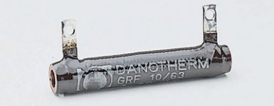
The trick I'm going to play on this build is to utilize air-cooled resistors (Danotherm GRF12/102 22R 50W). This way the mosfet will have the entire 0,5'C/W heatsink all by it self. It is enterely scaleable. Two points must be adjusted for different supply voltages:
1) Source voltage (operating point) on mosfet is set by the voltage divider formed by the 15K and 47K lifted 4V on the gate. It is set up to give 0,67 times the supply voltage at the Source, and 2) the load resistor(s) should be scaled to atleast 2 times the expected current draw. (7W in 8 ohms is 1,35A)
Have fun
Here is the schematic of the OTA version I am going to build sometime during this winter... To keep my feet warm when the snow is falling down thick
The design is very flexible, you can throw almost any part you have got at it, and chances are that it will work The trick I'm going to play on this build is to utilize air-cooled resistors (Danotherm GRF12/102 22R 50W). This way the mosfet will have the entire 0,5'C/W heatsink all by it self. It is enterely scaleable. Two points must be adjusted for different supply voltages:
1) Source voltage (operating point) on mosfet is set by the voltage divider formed by the 15K and 47K lifted 4V on the gate. It is set up to give 0,67 times the supply voltage at the Source, and 2) the load resistor(s) should be scaled to atleast 2 times the expected current draw. (7W in 8 ohms is 1,35A)
Have fun
Attachments

Mad_K said:I while back I posted a amplifier design with only one transistor.
I named it SEWA (Seven Watt Amplifier).
It seems most people interested in the design actually wanted LESS power (power dissipation I guess).
While the SEWA design has evolved into something different (coming later),
I have renamed this design OTA - One Transistor Amplifier.
Attached is the revised schematic.
Enjoy!
And please let me/us know if you decide to try it
Idea is perfect!
Start with one power transistor.
And go on from there to improve circuit.
Adding only things that will improve in any way
somthing that you can enjoy!
Hy there ,
I' ve started the construction of my amp .
Here there are some pictures of the mounting , without any PCB .
I' m still waiting for the capacitors in order to go on with this project .
I 'll be back soon as possible !
@ + Philippe.
I' ve started the construction of my amp .
Here there are some pictures of the mounting , without any PCB .
I' m still waiting for the capacitors in order to go on with this project .
An externally hosted image should be here but it was not working when we last tested it.
An externally hosted image should be here but it was not working when we last tested it.
An externally hosted image should be here but it was not working when we last tested it.
An externally hosted image should be here but it was not working when we last tested it.
I 'll be back soon as possible !
@ + Philippe.
Hy Mad_K
The resistors are 100 W , but I don' t know if they are Arcol :
And the Heatsinks look like this :
Just another question for you Mad_K :
which is the main difference between OTA and SEWA ?
@ + Philippe .
The resistors are 100 W , but I don' t know if they are Arcol :
An externally hosted image should be here but it was not working when we last tested it.
And the Heatsinks look like this :
An externally hosted image should be here but it was not working when we last tested it.
Just another question for you Mad_K :
which is the main difference between OTA and SEWA ?
@ + Philippe .
- Status
- This old topic is closed. If you want to reopen this topic, contact a moderator using the "Report Post" button.
- Home
- Amplifiers
- Pass Labs
- OTA - One Transistor Amplifier