High fellow searchers of the perfect sound!
You have built the F2 -
Now it's time to build the F3.
The simplified schematic posted on the web looks easy and simple enough!
All you have to do is to figure out plausible values for 3 resistors: R1, R2, and R3.
Mr Pass already has directions for current sources. I understand that one could even start with MOSFETS instead of JFETS.
Mr. Pass says that his cascode design is better than all the Zen versions. If that is so, then its time to go on from the F2. I have built the original Zen and updated it a few times, so I'm ready to go.
Since I have almost no electronics knowledge any experienced advice would be apprecieated!
Here is the simplified schematic for the F3 amplifier. As you can see we need 3 resistor values. I assume that I can use the basic current source that was as in Zen Variations Part 2. Volts would be about 25 after going through the regulation process.
Attachments
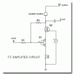
The F3 uses a modulated CCS that, as far as I recall, was made to optimize the distortion-figures of the Jfet. Also it is assumed to use a regulated supply. My guess is that the regulator could be modulated by the output to squeeze out a bit more effect of the Jfet. Another possibillity is that NP used 2 output devices in paralel to get the 15 watts. All in all, I dont think its easy to backengineer the F3I assume that I can use the basic current source that was as in Zen Variations Part 2
") But by all means, continue Maybe an excact clone isnt necessary to get a fine sounding amp. I think that a Zen (or Aleph) CCS and regulated supply sounds really good to start with
But by all means, continue Maybe an excact clone isnt necessary to get a fine sounding amp. I think that a Zen (or Aleph) CCS and regulated supply sounds really good to start with Steen
Hi Steen, auriontoledo and lineup,
The F3 is Cascode Modulated as illustrated by NP here:
http://www.diyaudio.com/forums/showthread.php?s=&threadid=64292&perpage=10&highlight=&pagenumber=4
It has a CCS but not modulated as in Aleph; more like Zen CCS. It has a regulated PS as mentioned in the Owner's Manual. It should have an unregulated rail of 50V as NP has a warehouse full of Plitron 300VA 18V-0-18V transformers As for the gain circuit I'm leaning more on the 2nd one he posted as the closest to the F3.
I'm hoping NP will post the circuit by the time the Jfets get in our hands.
Allan
The F3 is Cascode Modulated as illustrated by NP here:
http://www.diyaudio.com/forums/showthread.php?s=&threadid=64292&perpage=10&highlight=&pagenumber=4
It has a CCS but not modulated as in Aleph; more like Zen CCS. It has a regulated PS as mentioned in the Owner's Manual. It should have an unregulated rail of 50V as NP has a warehouse full of Plitron 300VA 18V-0-18V transformers
As for the gain circuit I'm leaning more on the 2nd one he posted as the closest to the F3.I'm hoping NP will post the circuit by the time the Jfets get in our hands.
Allan
Blues said:Hi Steen, auriontoledo and lineup,
The F3 is Cascode Modulated as illustrated by NP here:
http://www.diyaudio.com/forums/showthread.php?s=&threadid=64292&perpage=10&highlight=&pagenumber=4
It has a CCS but not modulated as in Aleph; more like Zen CCS. It has a regulated PS as mentioned in the Owner's Manual. It should have an unregulated rail of 50V as NP has a warehouse full of Plitron 300VA 18V-0-18V transformers
Actually, there is an Aleph current source on the top, and the
modulation on the Vds of the JFET is accomplished by means
other than described in the referenced post.
Fear not, it will all be revealed in the end.
I think we can make a good amp without make an exact copy of F3.
Besides, how fun is just copying?
We now know the basic way to setup a Cascoded JFET.
The current source can be solved in various ways.
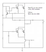
We can call this version:
PJF1 ( Power JFet version 1 ).
Hope we can get assistance from good guys in this field like:
Great Collins
Noss Palson
moisturetech
Geek Enshine
apeifiermuru
carelessfm
Upper Popes
and all the others
Besides, how fun is just copying?
We now know the basic way to setup a Cascoded JFET.
The current source can be solved in various ways.
We can call this version:
PJF1 ( Power JFet version 1 ).
Hope we can get assistance from good guys in this field like:
Great Collins
Noss Palson
moisturetech
Geek Enshine
apeifiermuru
carelessfm
Upper Popes
and all the others
Thank You, for the info Mr. Pass! Will this be a deal where after the "100" units are sold, you will publish the service manual? (ie; the end) How are sales doing on the F3?
Might we squeeze another hint? Are you useing active components to drive/modulate the cascode, or a passive approach similar to Zen8???
Thanks
Might we squeeze another hint? Are you useing active components to drive/modulate the cascode, or a passive approach similar to Zen8???
Thanks
Well what a coincidence! Mr Pass uses the Aleph current source in the F3.
I stopped fiddling around with/improving my Zen amp when I hit the Aleph current source described by Mr. Pass in Zen Variations - Part two. This means that I can leave it in my amp!! What a joy!
All I have to do is
1. rip out the 10uF input cap.
2. R2 of the "F3 simplified circuit already exists in my amp as 47K.
3. R1 I can try as 221R.
4. R3, from reading others attempts, would probably be anywhere from .22 to 1R.
5. That V with the circle aroung it can be a poti - maybe I'll move my 25k from the gate of Q1 over to the source as in the F3 circuit.
Voila! Finished!
Now I'll slowly, carefully put it into practice, using MOSFETs until I get ahold of JFETs. Perhaps, I'll start with a lower voltage and sniff for smoke.
I agree that we should try to make something different - even better - then the F3. With me it will only be through intuition and chance, as, like I wrote before, I have practically no knowledge of electronics other than through building Mr. Pass' projects.
Thank you Mr Pass for making everything possible!
OK, here's some more breadcrumbs:
You will want to note that the comments I posted on 12/31
on JFET matching apply to this circuit, so now you have the
Source resistor values if you test for the Vgs.
The bias current is about 1.6 to 1.7A, which is .4 ohm on the
Source of the Aleph CS transistor.
As an additional valuable piece of information, the DC output on
the Drain of the cascode is adjusted by the Gate voltage of the
Cascode Mosfet, which sets the Vds of the JFET. For a regulated
supply of 41V, the output DC value is about 21V.
Also, the Vds modulation is strictly that of the AC voltage across
the Source resistance to ground and the varying AC drop of the
Source voltage of the cascode transistor.
Lastly, this circuit will tolerate a wide range of current gain
settings on the Aleph source, anywhere from 0 to 80%, so you
can play with it to your heart's content.
Netlist said:Why is it that the current gain setting is so tolerant in this design compared to the ideal number of 50% in the AlephX?
The "ideal" number is simply the most efficient. If you run a
higher bias current, you can increase the gain setting of the
current source without shutting it off. At the point where the
bias current is equal to the peak value of the output current,
it does not shut off at all, and you can run it up toward 100%,
but the efficiency is about 1/2 that of the 50% gain case.
This is not to say that any particular setting is the best - that
depends highly on the circuit and on the criteria for quality. As
you probably know, the best objectively measured value is not
always the best sounding.
I think we can have any myway number.
I fully agree with you that having one is the most simple way.
As a fact, Aleph 30 has three for about 0.5A each, FYI.
My circuit shows two pairs of MOSFETs per channel. But, I have intention to have one pair more there for the active regulation.
My F1 with dual MOSFETs is working great (sound). So why not . . . ?
Regards
jh
- Status
- This old topic is closed. If you want to reopen this topic, contact a moderator using the "Report Post" button.
- Home
- Amplifiers
- Pass Labs
- Time to build the F3