Hello!
I'm happy to report that our aleph 5 project is making very good progress indeed. We are three guys building six monoblocks in total.
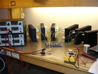
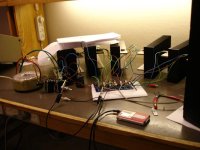
We finished soldering two days ago and tested them without fets first. Another post here in the forum told us that connecting the common point of C6, C8 and R7 to earth would allow us to measure as if the fets were there. All six pcb's measured fine.Yesterday we connected fets to one pcb and gradually applied voltage. A tense moment") But everything worked fine, including all the measurements. Now we had the courage to try some music, and music there was! Sweet undistorted music, although the labspeaker certainly has seen better days. After this success we hooked up our psu. Voltage on the rails was 41,2V. This is unconnected. Another tense moment as we connected everything and applied power... A slight hum from the toroid, and then silence. The toroid hum fades away and the speaker is dead silent. Nice!
But everything worked fine, including all the measurements. Now we had the courage to try some music, and music there was! Sweet undistorted music, although the labspeaker certainly has seen better days. After this success we hooked up our psu. Voltage on the rails was 41,2V. This is unconnected. Another tense moment as we connected everything and applied power... A slight hum from the toroid, and then silence. The toroid hum fades away and the speaker is dead silent. Nice!
Measuring R14 and Q5 gave us 5,12V. A bit higher than what the service manual suggests but is a result of the higher rail voltage? Z5 read 9,0V. Dc on the output was 12mV and ripple from the psu 40mV. IRF9610 are matched but IRFP240 aren't. This being a test run after all.
Hopefully the measurements will stay the same after averything is assembled.
A thanks to Mr. Pass for his designs and support to diy'ers. And also to this forum of course.
Eystein.
I'm happy to report that our aleph 5 project is making very good progress indeed. We are three guys building six monoblocks in total.
We finished soldering two days ago and tested them without fets first. Another post here in the forum told us that connecting the common point of C6, C8 and R7 to earth would allow us to measure as if the fets were there. All six pcb's measured fine.Yesterday we connected fets to one pcb and gradually applied voltage. A tense moment
But everything worked fine, including all the measurements. Now we had the courage to try some music, and music there was! Sweet undistorted music, although the labspeaker certainly has seen better days. After this success we hooked up our psu. Voltage on the rails was 41,2V. This is unconnected. Another tense moment as we connected everything and applied power... A slight hum from the toroid, and then silence. The toroid hum fades away and the speaker is dead silent. Nice! Measuring R14 and Q5 gave us 5,12V. A bit higher than what the service manual suggests but is a result of the higher rail voltage? Z5 read 9,0V. Dc on the output was 12mV and ripple from the psu 40mV. IRF9610 are matched but IRFP240 aren't. This being a test run after all.
Hopefully the measurements will stay the same after averything is assembled.
A thanks to Mr. Pass for his designs and support to diy'ers. And also to this forum of course.
Eystein.
Llafriel, nice pics
You can just skip the insulators then Very cool
If you are building Aleph 5's, which have 2x3 fets in parallel, you really do need to match them 3 fets in parralel
Steen
Thats a clever idea to bring down thermal resistanceIs this the best heatsinked Aleph?
You can just skip the insulators then
Very cool If you are building Aleph 5's, which have 2x3 fets in parallel, you really do need to match them 3 fets in parralel
Steen
hello
your radiators are MF30-2F-151.5 Conrad ? are they ?
you put one by channel of them?
if the answer is yes, be carefull, dissipation is not sufficient !
if the answer is no, it's all good...
for 36v and bias 1.9A, radiators 300x225x50 + 150x225x40 are not sufficient, for one channel Delta T = 40°C
I use fan...120mm,12V / 7V
Phill
your radiators are MF30-2F-151.5 Conrad ? are they ?
you put one by channel of them?
if the answer is yes, be carefull, dissipation is not sufficient !
if the answer is no, it's all good...
for 36v and bias 1.9A, radiators 300x225x50 + 150x225x40 are not sufficient, for one channel
Delta T = 40°CI use fan...120mm,12V / 7V
Phill
Thanks for the replies guys.
The fets weren't matched because it was a test run. We've already matched fets but didn't want to fry the good ones. We'll use them for the final assembly. The heatsinks are indeed from conrad. We'll use two for each channel so we should be on the safe side.
The fets weren't matched because it was a test run. We've already matched fets but didn't want to fry the good ones. We'll use them for the final assembly. The heatsinks are indeed from conrad. We'll use two for each channel so we should be on the safe side.
PheewWe've already matched fets but didn't want to fry the good ones.
You seem to be on top of things, then Happy listening, cause thats what it will be Very nice project, as it seems.Steen
Update
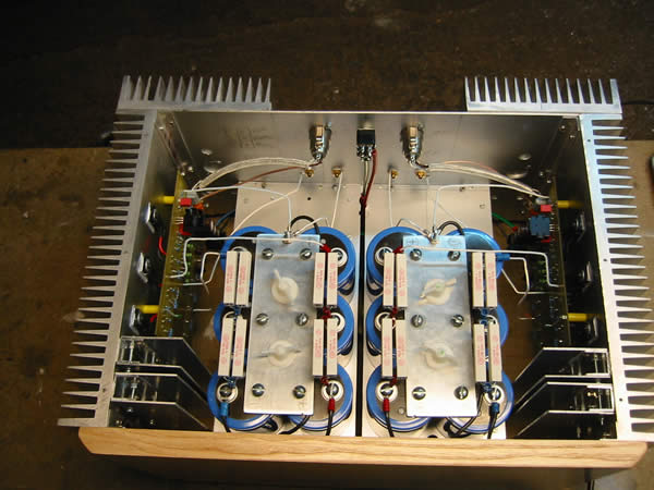
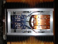
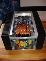
An update of the amplifiers. Two monoblocks are finished so far, exterior is not finished though. Heatsinks measure 50C after an hour or so. I get 0-5mV and 7-11mV dc. I'm not getting any stable readings here, is this the multimeters fault?
Naked amplifier:
An update of the amplifiers. Two monoblocks are finished so far, exterior is not finished though. Heatsinks measure 50C after an hour or so. I get 0-5mV and 7-11mV dc. I'm not getting any stable readings here, is this the multimeters fault?
Naked amplifier:
Attachments
- Status
- This old topic is closed. If you want to reopen this topic, contact a moderator using the "Report Post" button.
- Home
- Amplifiers
- Pass Labs
- Aleph 5 progress report