Dumb questions
First of all, thanks for putting this together. Iassume sometime in the future you will offer PCB's to build.
Do most use 60 - 80 volt rails for this circuit? Never could understand why the preamp rails are so high. Have a power amp whith 13 volt rails, seems the rail voltage should be the other way around.
Also looking at the IRF610 I originally thought of getting some IR brand from digikey. Then found some Samsung brand. Does everyone use IR type for the BOSOZ type circuits?
A friend tells me that IRF510 will work in most circuits using IRF610 and sound better. Think it is more as a driver application, but may try. The one at the bottom may be a place to start.
I will have to try this, been using the same circuit for line stage for a couple years. Time to give something else a listen.
George
Do most use 60 - 80 volt rails for this circuit?
With mosfets, yes. Running the higher railvoltages gives much improved performance. Better linearity in the audioband and less noise.
IR devices has some of the lowest input capacitance. Look for the Ciss value in the datasheets. The lower the better. (Higher Ciss, gives more high frequency distortion.) The 510 and 610's are just different in rating (volt/amps) they are fairly similar otherwise.
You might be able to find devices that are just as good, but I havent yet")
Steen
With mosfets, yes. Running the higher railvoltages gives much improved performance. Better linearity in the audioband and less noise.
IR devices has some of the lowest input capacitance. Look for the Ciss value in the datasheets. The lower the better. (Higher Ciss, gives more high frequency distortion.) The 510 and 610's are just different in rating (volt/amps) they are fairly similar otherwise.
You might be able to find devices that are just as good, but I havent yet
Steen
Re: Dumb questions
George,
I don't know about "better" but I can say that I've tried it with IRF510's (non-Xified BOSOZ with CCS) and also IRFD110's and it sounded fine with either one.
Knowing that in my system I'd never need more than 1V out, I used lower rail voltages, but also smaller drain resistors. (CCS in the source legs) As a result the operating point of the MOSFETs were more or less the same as in the article.
eL
Panelhead said:A friend tells me that IRF510 will work in most circuits using IRF610 and sound better.
George,
I don't know about "better" but I can say that I've tried it with IRF510's (non-Xified BOSOZ with CCS) and also IRFD110's and it sounded fine with either one.
Knowing that in my system I'd never need more than 1V out, I used lower rail voltages, but also smaller drain resistors. (CCS in the source legs) As a result the operating point of the MOSFETs were more or less the same as in the article.
eL
Request for help.
Hi folks,
First I want to thank everyone for their kind words and helpful tips.
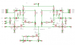
Now I need a little help with this circuit. I am not sure about ratings of certain parts, especially the resistors.
Particularly:
R3, and R4
R1, R2, R6, and R7
It looks like the other resistors can be standard .25W metal film types correct?
Also what voltage rating should C1 be 100V?.
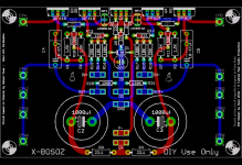
Also I plan on resizing C2 and C3 to be 25mm diameter and 10mm LS which should fit most common snap-in 100-200V 1000uf caps. Right now it is set up of 7.mm straight lead types.
Any help with these details from those familiar with the circuit is great appreciated.
Cheers!
Russ
Hi folks,
First I want to thank everyone for their kind words and helpful tips.
Now I need a little help with this circuit. I am not sure about ratings of certain parts, especially the resistors.
Particularly:
R3, and R4
R1, R2, R6, and R7
It looks like the other resistors can be standard .25W metal film types correct?
Also what voltage rating should C1 be 100V?.
Also I plan on resizing C2 and C3 to be 25mm diameter and 10mm LS which should fit most common snap-in 100-200V 1000uf caps. Right now it is set up of 7.mm straight lead types.
Any help with these details from those familiar with the circuit is great appreciated.
Cheers!
Russ
Russ,
In my circuit, I used a single 1/2W resistor where you have split it to two resistors (R3 and R4). I believe you can use 1/4W with your circuit.
I used a single 5W resistor where you are using R1/R6 in parallel. For R1, R2, R6, R7 I would recommend 3W rated resistors as a minimum.
As to C1, its voltage rating will depend on the value of your negative rail voltage, which can be in the range of 10-20 volts. I don't think you will need a 100V rated cap there.
Lastly there is one set of resistors missing, which I included when I built my preamp, but missed including on the schematics. Q2 and Q3 need 221 ohm gate resistors in the connection to the voltage references. (My Bad ).
).
Otherwise it is looking great.
Cheers, Terry
In my circuit, I used a single 1/2W resistor where you have split it to two resistors (R3 and R4). I believe you can use 1/4W with your circuit.
I used a single 5W resistor where you are using R1/R6 in parallel. For R1, R2, R6, R7 I would recommend 3W rated resistors as a minimum.
As to C1, its voltage rating will depend on the value of your negative rail voltage, which can be in the range of 10-20 volts. I don't think you will need a 100V rated cap there.
Lastly there is one set of resistors missing, which I included when I built my preamp, but missed including on the schematics. Q2 and Q3 need 221 ohm gate resistors in the connection to the voltage references. (My Bad
).Otherwise it is looking great.
Cheers, Terry
gate stoppers and another dummy question
Plan on using pots to control volume in mine. Do they need to be 10K? Seems that the input capacitance was high enough that a 10K pot was recommended to prevent high end roll off.
Have several 25K laying around unused. Hate to buy more to use here.
Also, output coupling cap selection. What is the range of dc seen here? If it is real low, may try to use some output transformers to do the balanced to single ended conversion. Prefer iron to caps where possible. Do not want to use both.
George

pic
Good call Terry. Hey, I was just getting used to the new picture then you switched back.
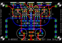
This comment is for those of you who used Nelson's patent designs in a PCB, such as the X design here.
Please print the following legend: "U.S. Patent No(s).__________, __________" (include the numbers) on the PCB itself. Also, get Nelson's permission to make these boards, but seems like everyone does this anyway so the #'s are more important.
Doing so will put the public on notice of the patent, and will protect Nelson's rights should anyone infringe the patent. More specifically, putting a patent no. on these boards in 2005 will allow Nelson to get royalties against infringers back to 2005 should anyone infringe his patents. Otherwise, should Nelson win a case agains an infringer, Nelson would only gets $$ back to the date he put the infringers on notice via a notice letter or to the date he sued them (the earlier).
So its better for us (and for Nelson) to see if we can get Nelson to give approval for the boards and for the boards to carry the patent ##'s. In my view, all people using his patents should attempt to do both (permission and #'s).
Good call Terry. Hey, I was just getting used to the new picture then you switched back.
This comment is for those of you who used Nelson's patent designs in a PCB, such as the X design here.
Please print the following legend: "U.S. Patent No(s).__________, __________" (include the numbers) on the PCB itself. Also, get Nelson's permission to make these boards, but seems like everyone does this anyway so the #'s are more important.
Doing so will put the public on notice of the patent, and will protect Nelson's rights should anyone infringe the patent. More specifically, putting a patent no. on these boards in 2005 will allow Nelson to get royalties against infringers back to 2005 should anyone infringe his patents. Otherwise, should Nelson win a case agains an infringer, Nelson would only gets $$ back to the date he put the infringers on notice via a notice letter or to the date he sued them (the earlier).
So its better for us (and for Nelson) to see if we can get Nelson to give approval for the boards and for the boards to carry the patent ##'s. In my view, all people using his patents should attempt to do both (permission and #'s).
Power Supply?
Russ,
The last thing I would want to do is add more work to your plate, but you do such excellent work and I have been impressed that both beta sets I got from you worked right away.
However, have you given any consideration to a power supply board to go with these, or should we consider another source? I still have an aversion to point wiring.
Hi Craig,
I am working on the PS right now. It will be slightly different from Kari's, but not much. I think it will like either have 2 x 4700uf or 4 x 4700uf on the rails. The constraint is space. I can only make a ~4" x ~3.2" PCB with the version of eagle I have.
Cheers!
Russ
I am working on the PS right now. It will be slightly different from Kari's, but not much. I think it will like either have 2 x 4700uf or 4 x 4700uf on the rails. The constraint is space. I can only make a ~4" x ~3.2" PCB with the version of eagle I have.
Cheers!
Russ
fcel said:Any chance of publishing a part list with part numbers and vendor's name - just like what Brian did for the mini-A?
Brian Donegan and I will probably produce kits for this AMP/PS and for those who only want PCBs we will provide a complete BOM.
Cheers!
Russ
- Home
- Amplifiers
- Pass Labs
- My Take on X-BOSOZ