Hi all,
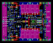
as I would like the enter the "Alephworld", I' ve designed an Aleph-X PCB.
Due to the constraints of my PCB Editor (Eagle demo Version), the board is very compact (4" x 3.20"), and it' s not been very easy to stuff all the components on it.
Now, given that I'm not that experienced in PCB design, I would like to hear the opinion of the more knowledgeable people on this forum.
Suggestions, constructive critics, flames are all most welcome!
Cheers,
Bruno
Attachments
 <ahem>
This is pretty much identical to the 3yo standard AX board that just about everyone around here either owns or has seen.
Since everthing appears to be laid out in about the same place, if there are no mistakes, it should work.
If you are trying to actually build the amp for cheap a few people should have a bunch of the board stashed away somoene should be able to sell you a pair for no more than five dollars each. These are 4 oz Cu with the solder mask and the works. You can beat that.
Unfortunately, I am all out of mine.
Hi all!
Thanks a lot for all the answers, it' s nice to be part of such a great community!
Well, given the intrinsic, simmetrical structure of the Aleph-X, I guess it would be quite difficult/illogical to lay out the parts in a totally different way. Nevertheless, there' s one difference: I added a heatsink for the input MOSFETs, to improve the thermal coupling. I know, in previous threads it has been said this is not necessary, but it makes me feel better...
Well, I' m not trying to build it for cheap (although I do not even want to spend a fortune), my primary goal is really to build a good amp AND to improve my personal PCB design skills. Moreover, reading other threads, it looks like there' s not many of the previous boards left, as there are other people looking for them without apparent success.
Cheers,
Bruno
Thanks a lot for all the answers, it' s nice to be part of such a great community!
grataku said:This is pretty much identical to the 3yo standard AX board that just about everyone around here either owns or has seen.
Since everthing appears to be laid out in about the same place, if there are no mistakes, it should work.
Well, given the intrinsic, simmetrical structure of the Aleph-X, I guess it would be quite difficult/illogical to lay out the parts in a totally different way. Nevertheless, there' s one difference: I added a heatsink for the input MOSFETs, to improve the thermal coupling. I know, in previous threads it has been said this is not necessary, but it makes me feel better...
grataku said:If you are trying to actually build the amp for cheap a few people should have a bunch of the board stashed away somoene should be able to sell you a pair for no more than five dollars each.
Well, I' m not trying to build it for cheap (although I do not even want to spend a fortune), my primary goal is really to build a good amp AND to improve my personal PCB design skills. Moreover, reading other threads, it looks like there' s not many of the previous boards left, as there are other people looking for them without apparent success.
Cheers,
Bruno
Bruno,
the heatsink is absolutely unnecessary, I put a silpad and sqeezed the two mosfet together using a nylon screw.
These two will start dissipating enough to require heatsinking at around +/- 30V supply. You want them to get a little warm so that their temp. doesn't track RT and make the DC offset too enviroment dependent. The space would be put to better use by the addition of two nice PP input caps. which, on the other hand, I found to be absolutely necessary.
2nd Version
Hi all,
thanks to you all for your comments!
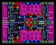
I was thinking that it would be nice to have on the PCB also the two 33R, 3W resistors from output to gnd, so... well... here' s the 2nd version of the board. Any comments?
Hi grataku, thanks a lot for your valuable input!
Well, if I do not want to use the heatsink I can always bend the pins of the two mosfets in order to squeeze them together.
As for the input caps, do you think they' re necessary if the preamp already has some caps on the outputs?
Cheers,
Bruno
Hi all,
thanks to you all for your comments!
I was thinking that it would be nice to have on the PCB also the two 33R, 3W resistors from output to gnd, so... well... here' s the 2nd version of the board. Any comments?
grataku said:Bruno,
the heatsink is absolutely unnecessary, I put a silpad and sqeezed the two mosfet together using a nylon screw.
These two will start dissipating enough to require heatsinking at around +/- 30V supply. You want them to get a little warm so that their temp. doesn't track RT and make the DC offset too enviroment dependent. The space would be put to better use by the addition of two nice PP input caps. which, on the other hand, I found to be absolutely necessary.
Hi grataku, thanks a lot for your valuable input!
Well, if I do not want to use the heatsink I can always bend the pins of the two mosfets in order to squeeze them together.
As for the input caps, do you think they' re necessary if the preamp already has some caps on the outputs?
Cheers,
Bruno
Attachments
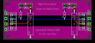
Carondimonio said:And here' s the driver board (4" x 1.80"):
I would consider mounting the fets on the short axis of the driver board, to keep the hotspots further apart, you could loose the mounting holes and lay the driver board onto the fets (legs bent @ 90deg)
just my 0.5 cents, Keep at it as like you pointed out there are people looking for these boards.
Carondimonio said:Hi Mark,
sorry for the late answer, I've been away on a business trip.
Thanks a lot for the suggestion, I will work on it in the next days.
Cheers,
Bruno
P.S.: Any comment on the new version of the main PCB?
Bruno,
I have not yet left the plain old aleph world and moved onto the X, it is on the list of things to do before I expire. Those that have built one would provide you with better feedback than I.
The things that I would try to do to the main board if you wanted to help the community by offering a group buy (oh dear did some one say group buy) would be:
1. Move the mounting holes in a bit they look a bit close to the “se” connection (its hard to see with no scale or files)
2. Enlarge the keep out around the mounting holes (it may just be me that likes to use hex button head screws to mount pcb’s and or metal hex standoffs).
3. Provide some extra vias in between the existing 0.47r resistors so you can add extra resistors on top of the existing ones. (if you happened to have a stash of 1r resistors you could use 8 per side, Assuming the X is like the plain Aleph also really handy to make different power versions)
4. I know the heatsink has been mentioned but I don’t like the idea of having it directly on top of tracks. Like you pointed out you could leave it out if you desire, I would leave it as it is (unless you really need the space) but probably put a length of alloy or copper between the fets (insulated).
That’s it for now, please send me the brd and circuit files if you want further input.
Version 3
Hi all,
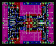
well, I didn' t have much time lately to work on this project, but now I' ve made some changes to the previous version.
1.: Done.
2.: Done.
3.: Done.
4.: Well, at the moment I decided to live the heatsink as it is. It can be left out or it can be replaced by a small block of copper or a smaller heatsink. If installed as it is, the solder mask will anyway isolate the tracks from the heatsink.
Any thoughts?
Cheers,
Bruno
P.S.: Mark, YGM!
Hi all,
well, I didn' t have much time lately to work on this project, but now I' ve made some changes to the previous version.
mark stones said:
Bruno,
I have not yet left the plain old aleph world and moved onto the X, it is on the list of things to do before I expire. Those that have built one would provide you with better feedback than I.
The things that I would try to do to the main board if you wanted to help the community by offering a group buy (oh dear did some one say group buy) would be:
1. Move the mounting holes in a bit they look a bit close to the “se” connection (its hard to see with no scale or files)
2. Enlarge the keep out around the mounting holes (it may just be me that likes to use hex button head screws to mount pcb’s and or metal hex standoffs).
3. Provide some extra vias in between the existing 0.47r resistors so you can add extra resistors on top of the existing ones. (if you happened to have a stash of 1r resistors you could use 8 per side, Assuming the X is like the plain Aleph also really handy to make different power versions)
4. I know the heatsink has been mentioned but I don’t like the idea of having it directly on top of tracks. Like you pointed out you could leave it out if you desire, I would leave it as it is (unless you really need the space) but probably put a length of alloy or copper between the fets (insulated).
That’s it for now, please send me the brd and circuit files if you want further input.
1.: Done.
2.: Done.
3.: Done.
4.: Well, at the moment I decided to live the heatsink as it is. It can be left out or it can be replaced by a small block of copper or a smaller heatsink. If installed as it is, the solder mask will anyway isolate the tracks from the heatsink.
Any thoughts?
Cheers,
Bruno
P.S.: Mark, YGM!

 literally, before thinking that would work. Too easily scratched. I would use a mica insulator or something between them.
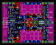
Input caps:
I thought what you thought, I got caps on the preamp what do I need caps in the input for? Right?...Wrong.
I don't fully understand why but try it out and see for yourself, the dc ot the output is much better behaved with the input caps.
I would make provisions for the caps before hand rather than putting them in on the fly as an afterthought.
Unfortunately, the input impedance of the amp is on the low end side so the caps need to be more than 1uF and the PP kind tend to be large.
Banned
Joined 2002
Hi grataku,
hmmm... well, I' ll try to fit the input caps, I guess 2 uF should be OK, what do you think?
Hi jleaman,
the output boards are daisy-chainable, there are also pads for screw terminals with a 200 mil step for this purpose (and, of course, normal soldering pads).
As for the group buy, well... I do not know, it depends on how many people are interested.
Cheers,
Bruno
- Status
- This old topic is closed. If you want to reopen this topic, contact a moderator using the "Report Post" button.
- Home
- Amplifiers
- Pass Labs
- My Aleph-X compact PCB