30Vx3,5A=105W/ch. Hmm.. 0,25'C/W heatsink per channel, IRFP250, 600VA trafo, 47Kuf caps. BOZ with VDrain@25V in front. Oh, mama
Ohhh! It is too much for me.....

What about on +24Vdc or even lower?
How sensitive will they be?
Double 92dB drivers = 95dB
Tyimo
95dB =  You can run a stock SEWA
24V would be ideal (18VAC trafo, loads down to 22,5V) for 4 ohm. With 2A bias it can do 8W. I would probably adjust the bias up a notch (as much as the heatsinks can take) 2,5-3A would be nice 3A will give you about 13W.
22,5V, 3A=67,5W => 0,4C'W heatsink.
With the IRFP250 you could get away with a 0,5'C/W (actual) heatsink, but it will be hot; 60'C But the mosfet will stay happy @ 67,5/2 x (0,65+0,35 (al-oxide washer+grease)) +60=34+60=94'C junction temp.
You can run a stock SEWA 24V would be ideal (18VAC trafo, loads down to 22,5V) for 4 ohm. With 2A bias it can do 8W. I would probably adjust the bias up a notch (as much as the heatsinks can take) 2,5-3A would be nice
3A will give you about 13W.22,5V, 3A=67,5W => 0,4C'W heatsink.
With the IRFP250 you could get away with a 0,5'C/W (actual) heatsink, but it will be hot; 60'C
But the mosfet will stay happy @ 67,5/2 x (0,65+0,35 (al-oxide washer+grease)) +60=34+60=94'C junction temp. EDCOR’s XSM transformers are not gapped.

Just out of curiosity,do you have a schema how to do?Never done such a thing before.
to Parafeed or Not to Parafeed that is..........
This post is an example of parafeed, http://www.diyaudio.com/forums/showthread.php?postid=986565#post986565
Parafeed is feeding a transformer through a capacitor and loading the plate with an inductor, not allowing the DC current through the transformer
Here is a little light reading on the subject from Steve Bench
http://members.aol.com/sbench/outstru.html
Ryssen said:
Just out of curiosity,do you have a schema how to do?Never done such a thing before.
This post is an example of parafeed, http://www.diyaudio.com/forums/showthread.php?postid=986565#post986565
Parafeed is feeding a transformer through a capacitor and loading the plate with an inductor, not allowing the DC current through the transformer
Here is a little light reading on the subject from Steve Bench
http://members.aol.com/sbench/outstru.html
My long term plan is to build a bi- or tri-amped system
So here is the deal
To be able to use SEWA I could build BOZ as pre, and have multiple outputs - one with fixed full gain fore SEWA, and others with adjustable gain
Main attennuator on input could be a seperate TVC or simply a build in att
PROBLEM ? I recall to have read that PASS pre need main attennuator on output, with regards to stability ?
Comment on this, please
Mad_K said:The main difference is the mounting of the board/mosfets. The board also acceps a little larger filtering caps. The reason for the difference in price is the pcb size. I have 4 Rev.B boards and 9 Rev.C boards left.
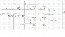
Rev.C schematic attached
8W
An externally hosted image should be here but it was not working when we last tested it.
http://perso.orange.fr/jm.plantefeve/sche.html
Hi DIGORA!
And? What should we do with this schematic?
Did you buid or listen it?
You should translate the text:
Greets:
Tyimo
And? What should we do with this schematic?
Did you buid or listen it?
You should translate the text:
Un seul transistor traite le signal: le BUZ900DP, la contre réaction disparaît. Très proche d'un pur générateur de courant, l'impédance du HP qui servait de convertisseur U/I "s'efface" pour une force appliquée à la menbrane directement image du courant généré. Ce principe est adapté aux transducteurs "large bande" à faible Qts et voies médium aigu en filtrage actif. Le gain est de 24 dB (x16). Ce schéma a une entrée référencée au "-" et non au "0". Du coup, le condonsateur de liaison se charge à la mise sous tension et la sortie haut-parleur doit être temporisée.
Greets:
Tyimo
Hi Mads!
Could you tell me the voltage values in your BOZ? I mean the measured values on the Gate and Drain? (and on the Source too.)
A friend of me has some problem and it would be help for him.
Maybe He will write here him self too.
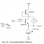
And one question from me: could you draw or show me a cascoded source follower circuit? Just to see how is it looks like. I have never seen any....
Maybe it would be a good starting point to build something with my power Jfets.
Greets:
Tyimo
Could you tell me the voltage values in your BOZ? I mean the measured values on the Gate and Drain? (and on the Source too.)
A friend of me has some problem and it would be help for him.
Maybe He will write here him self too.
And one question from me: could you draw or show me a cascoded source follower circuit? Just to see how is it looks like. I have never seen any....
Maybe it would be a good starting point to build something with my power Jfets.
Greets:
Tyimo
Tyimo said:
Could you tell me the voltage values in your BOZ? I mean the measured values on the Gate and Drain? (and on the Source too.)
The voltage values is in the schematic (attached) About 7,5V on the gate and 3,5V on the source actually. Adjusted to 25V on the Drain for a clean +/-20V output swing.
Attachments
Tyimo said:Hi Mads!
And one question from me: could you draw or show me a cascoded source follower circuit? Just to see how is it looks like. I have never seen any....
Maybe it would be a good starting point to build something with my power Jfets.
Greets:
Tyimo
From Nelson's cascode article, Fig.7b
Attachments
Re: 36v 4A
Yes, that's how you paralell mosfets If you use the IRFP250 I don't think you need it though..
ruferto said:My first post.
Hi
give me your opinion.
Yes, that's how you paralell mosfets
If you use the IRFP250 I don't think you need it though..36v 4A Post #492
My first post.
Hi
give me your opinion.
You may run into problems, because the upper MosFets wont nessesarily share the current equally. You might have to give them a source-resistor each.
Thorstendriver stage
Hi
I'm thinking of adding a driver stage for SEWA.
The plan is to combine BOZ preamp and the SEWA
by removing some parts near the connection.
That is, removing output capacitor of BOZ (which is mod to have 15.5V output DC voltage),
and removing input bias network for SEWA (R1,R2,R3,R9,R10,C2...).
Directly couple the input signal to Q1's G Pin
Any comment for this?
Maybee this could be sommething:http://www.diyaudio.com/forums/showthread.php?s=&threadid=85727
I thougt of using 6c45,but changed my mind am going to try with a CF and a ECC86 before it..
I thougt of using 6c45,but changed my mind am going to try with a CF and a ECC86 before it..
Re: driver stage
This will work quite nice for a stock SEWA I have thought about it, but since I am continously swiching gear, I haven't bothered 
ACK2005 said:Hi
I'm thinking of adding a driver stage for SEWA.
The plan is to combine BOZ preamp and the SEWA
by removing some parts near the connection.
That is, removing output capacitor of BOZ (which is mod to have 15.5V output DC voltage),
and removing input bias network for SEWA (R1,R2,R3,R9,R10,C2...).
Directly couple the input signal to Q1's G Pin
Any comment for this?
This will work quite nice for a stock SEWA
I have thought about it, but since I am continously swiching gear, I haven't bothered - Status
- This old topic is closed. If you want to reopen this topic, contact a moderator using the "Report Post" button.
- Home
- Amplifiers
- Pass Labs
- SEWA - Seven Watt Amplifier