When designs are getting this many parts, it's a real aid to have a good pcb. I have designed a pcb that is really easy to make for yourself. It measures 33x100mm, single sided, and features only industry standard parts which should be easy to get in most parts of the world.
Attachments
JRKO said:I cant seem to download the last .pdf. Is it just me? I see 15 others have managed
psu.pdf
It is possible to download.
But when opened there is an error and it does not display correctly.
Error message:
Unknown token 'b*9.89' was found.
You better make a new version.
that was better
---------------------------------
If there is one thing I should change in SEWA rev1
is the bias resistor for MOSFET.
Now R2 is VERY HIGH, 330kOhm.
I would more like to have it 33k.
This of course means increase C2 input cap to 1uF, to get same bass rolloff.
Otherwise I have not anything to complain about.
Your SEWA circuit is a very nice amplifer.
lineup said:that was better
---------------------------------
Now R2 is VERY HIGH, 330kOhm.
I would more like to have it 33k.
.
And "djk" wants it at 470K, so you'll meet at the middle
")
I couldn't register any negative effects from raising it from 100K though.. Anyway, the point with 250K Zin is to make life easier on the preamp that is going to be driving it, and it makes for a nice pcb layout (with good components).
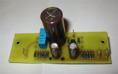
The power posts are 6,3mm FASTON PCB Blade as specified in the BOM. The small ones I use for input signal are often referred to as "testpoints" or "test lug". There are several types, but I use JT-1 from K&H. www.elfa.se/en product # 48-415-73. Now I have included them in the BOM
Attachments
Mad_K said:And "djk" wants it at 470K, so you'll meet at the middle
I couldn't register any negative effects from raising it from 100K though.. Anyway, the point with 250K Zin is to make life easier on the preamp that is going to be driving it, and it makes for a nice pcb layout (with good components).
There can be cases when you need a high input impedance.
Depends on what comes before power amp.
Personally I would feel bad using more than 22 kOhm input.
And my sources, CDplayer, Preamp, can easily drive downto 5 kOhm loads.
Today Normally used input impedance for power amps is:
10.000 - 22.000 Ohm
The rule is:
If you can,
keep input impedance as low as possible.
This will transport more micro currents ( uA, uAmpere )
in your signal cables,
even if you input voltage is a as low as 0.1 Volt RMS.
Of course everyone is free to choose whatever inputimpedance that suits them If you go to a polyester input cap (elfa # 65-525-09 ) 2u2/50V you can lower R2 to 22K and still use my PCB layout. I have no problems with noise pickup, the amp is DEAD SILENT. I can't see how loading the source more helps anything. What I know is that a polypropylen cap sounds better than a polyester 
If you go to a polyester input cap (elfa # 65-525-09 ) 2u2/50V you can lower R2 to 22K and still use my PCB layout. I have no problems with noise pickup, the amp is DEAD SILENT. I can't see how loading the source more helps anything. What I know is that a polypropylen cap sounds better than a polyester 
- Status
- This old topic is closed. If you want to reopen this topic, contact a moderator using the "Report Post" button.
- Home
- Amplifiers
- Pass Labs
- SEWA - Seven Watt Amplifier