Fuling said:
A 20-25W SE follower OTOH would be a fully realistic project,
the 100-150W of losses per channel wouldn´t be a problem for a pair of good heatsinks. Spreading the heat by using multiple Mosfets would probably be a great idea, same thing with putting a lot of effort into mounting them correctly on the heatsinks.
40V and 3A should be enough for just over 20W into 8 ohms.
Since I´m more interested in current capability than max power into a resistive 8 ohms load I´ll go for 32V rails and still pull 3A through the mosfets.
.
20-25W SE follower.... 100-150W of losses per channel
That is a fair and good estimation of the total power required
to make these Non Push-Pull Class A output stages.
Other ways to put it:
- We get out something like 10-20% of the idle Class A power running in output stage.
- It takes an idle power like 5-10 times larger, than the wanted output power.
There are several Nelson Pass Class A amplifier of this type
that have an efficiency of only like 10% or lower.
10 times more power dissipation than output power.
-------------------------------
Class A Amplifiers - Efficiency figures
1. Theoretical Maximal efficiency is for Push-Pull Class A: 50%
In practical circuits
with some drops across both NPN and PHP devices,
we can achieve ~40%.
2. For a CCS Class A, using Transistor constant current source Load in output stage:
Theoretical max: 25%
Practical circuits, like SEWA: ~20%
3. For using only One Power Resistor as output stage load, instead of CCS,
I do not remember the figure for theoretical max efficiency.
But in practical circuits, I think, this can be as low as: ~5%
lineup
Those efficiency figures looks correct to me.
Not sure about the efficiency of resistor loaded stages, my "Illegitime son of Zen" has an efficiency of about 6% or so if I remember correct. Can´t swear by my measurements either, so let´s leave it out of the discussion
One thing to remember is that low power amps seems less efficient than high power amps using the same topology, I guess the little losses we have everywhere plays a bigger role in smaller amps.
Pretend we loose 3V swing over the CCS and 1V over the source follower Mosfet, that would be 20% of a 20V rail but only 10% of a 40V rail.
Things like the transconductance changing with the drain current might also affect the efficiency I guess.
Still, I somehow seem to prefer the sound of smaller amps. I guess the input capacitance of smaller mosfets vs bigger mosfets might be reason enough to build small stuff if the speakers are fairly sensitive.
Hi!
For me too.
All right gentlemans! Let's back to my first question!
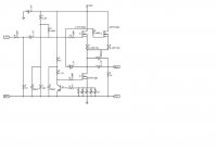
Could we use the original SEWA V1 circuit with the necessary modifications? Like my attached schematic?????
Everythinig is the same, only 1 more output device and the the necessary 0.22R/5W resistors to get equal current.
I would use 30V rails and 3 A. I think the SEWA CCS could still manage this value.
Greets:
Tyimo
Those efficiency figures looks correct to me.
For me too.
I think we can manage this.20-25W SE follower.... 100-150W of losses per channel
All right gentlemans! Let's back to my first question!
Could we use the original SEWA V1 circuit with the necessary modifications? Like my attached schematic?????
Everythinig is the same, only 1 more output device and the the necessary 0.22R/5W resistors to get equal current.
I would use 30V rails and 3 A. I think the SEWA CCS could still manage this value.
Greets:
Tyimo
Attachments
Tyimo said:Could we use the original SEWA V1 circuit with the necessary modifications?
Like my attached schematic?????
Everythinig is the same, only 1 more output device and the the necessary 0.22R/5W resistors to get equal current.
I would use 30V rails and 3 A.
I think the SEWA CCS could still manage this value.
.
The basic setup for SEWA would work fine.
Except for counting for more heat and power on the devices/resistors
and stronger power supply + supply filtering.
Also some components in input part may need to be adjusted a bit.
We may consider a driver transistor for those both BIG MOS.
Like one IRF9610.
I have seen this used in Pass Amplifiers.
I wonder if Mad_K. could give some comments?
I am not as good with calculating MOSFET, as I am with bipolar.
Because mathematical calculating is what 50% of amplifier design is about.
And 90% of these calculations are using Ohm's Law.
U = R x I
Voltage = Resistance x Current
Volt = Ohm x Ampere
Here is something for us to start with.
Tyimo first schematic suggestion:
http://www.diyaudio.com/forums/attachment.php?s=&postid=1069280&stamp=1164909483
lineup
30V and 3A should require no major changes from the SEWA schematic, only a trimpot in the bias voltage divider to set the quiescent point and some additional resistors in the CCS to raise the current.
30V rails won´t give any 20-25W into 8 ohms though, more like 12W or something.
The increased power dissipation per mosfet can be handled by changing to IRFP260, which is a 300W device (with horribly high input capacitance, so a buffer on the input might be a good idea).
30V rails won´t give any 20-25W into 8 ohms though, more like 12W or something.
The increased power dissipation per mosfet can be handled by changing to IRFP260, which is a 300W device (with horribly high input capacitance, so a buffer on the input might be a good idea).
Just use a stock SEWA with 35V caps and 5*1R 0,6W resistors (and 5K6 in bias network) to get 3A bias. I would use a 0,25'C/W heatsink and aluminium oxide washers for this. This would also be the largest SEWA I would consider. Any more heat per device and I would start paralleling devices. Remember to also paralell the CCS mosfets
Hi!
Yes.
For a 8ohm load, the 30V/3A amp would be voltage limited to only 10.6W and current limited to 35.9W( it is too much).
With 45V/2.5A the amp wouldbe:
voltage limited to 26.25W and
current limited to 24.99W.
I think it is realizable! Two output device and two ccs Fet.
What do you think?
Tyimo
30V rails won´t give any 20-25W into 8 ohms though, more like 12W or something.
Yes.
For a 8ohm load, the 30V/3A amp would be voltage limited to only 10.6W and current limited to 35.9W( it is too much).
With 45V/2.5A the amp wouldbe:
voltage limited to 26.25W and
current limited to 24.99W.
I think it is realizable! Two output device and two ccs Fet.
What do you think?
Tyimo
Re: Sewa Se 25w
Use 4 MOSFET.
And use separate source resistors for each device in CCS.
for example 2+ 2 resistors, or 3+3, or 4+ 4.
Even if you could use one in CCS it will get much hotter than the others.
And Nelson Pass runs his MOSFET rather colder. They will work better.
Remember, the important temperature is
- NOT temp at Heatsink
- NOT temp at Transistor Case
.... but it is temperature inside = junction temperature.
This value we can see in datasheet: max storage and junction temperature.
Formula for calculating junction temp: Tj = Tc + ( P x k )
Tj = temp junction, Tc = temp case,
k= degrees per watt, for example: 0.8 C/W
P = watt, power in transistor
Example:
If Tc = 60 C, k=1.0, P=watt in transistor=50
Tj = Tc + P x k
Tj= 60 + (50 x 1.0) degrees
Tj = 110 degrees C
Now it is good try to keep junction temperature like <=80 C.
At least not very nice to go above 100 C.
Even if most transistors can have 150 C max junction temperature.
===========================================
Maybe you could better use 4 x IRFP240. (or IRFP140)
I don't know, but I see they are much used.
Is there any difference?
Are there any other options for what N-Channel high power could be used here
for best results?
lineup
Mad_K said:Go for it! (dual mosfets might be wise)
Tyimo said:I think one CCS Fet could manage the 2.5A.
Would you check it please?[/B]
Use 4 MOSFET.
And use separate source resistors for each device in CCS.
for example 2+ 2 resistors, or 3+3, or 4+ 4.
Even if you could use one in CCS it will get much hotter than the others.
And Nelson Pass runs his MOSFET rather colder. They will work better.
Remember, the important temperature is
- NOT temp at Heatsink
- NOT temp at Transistor Case
.... but it is temperature inside = junction temperature.
This value we can see in datasheet: max storage and junction temperature.
Formula for calculating junction temp: Tj = Tc + ( P x k )
Tj = temp junction, Tc = temp case,
k= degrees per watt, for example: 0.8 C/W
P = watt, power in transistor
Example:
If Tc = 60 C, k=1.0, P=watt in transistor=50
Tj = Tc + P x k
Tj= 60 + (50 x 1.0) degrees
Tj = 110 degrees C
Now it is good try to keep junction temperature like <=80 C.
At least not very nice to go above 100 C.
Even if most transistors can have 150 C max junction temperature.
===========================================
Maybe you could better use 4 x IRFP240. (or IRFP140)
I don't know, but I see they are much used.
Is there any difference?
Are there any other options for what N-Channel high power could be used here
for best results?
lineup
Thanks Lineup!
I understand your suggestion, but I cann't believe that 2.5A would be too much for 1 IRFP150N in the CCS.
I donn't know how to connect the output caps in your double CCS version.
Could you help me with a drawing? I would like to use your way, if it is not so complicated.
Tyimo
I understand your suggestion, but I cann't believe that 2.5A would be too much for 1 IRFP150N in the CCS.
I donn't know how to connect the output caps in your double CCS version.
Could you help me with a drawing? I would like to use your way, if it is not so complicated.
Tyimo
I tried the Sewa with 2,7A,and my heatsinks got hot!!Well,I guess it depends on how big you heatsinks are.I understand your suggestion, but I cann't believe that 2.5A would be too much for 1 IRFP150N in the CCS.
okay
I will do some math!
Remember, this is what 50% of making a good power amplifier is about.
-------------------------------
Thermal resistances coefficients
I do not know what is the approximate ~ rating of your heatsink.
But I will use 0.5 C/W here.
Insulator bricks, I will use 0.4 C/W ( I asked Nelson one time. He agreed, 0.5 C/W is a fair value to use, to be safe )
IRFP150N, 0.95 C/W (this is thermal resistance form outside, case, to inside, junction)
Formula:
Tj = P x ( Rjc + Rcs + Rsa ) + Ta
Temperatures
Ta = ambient temp, air around heatsink, >= room temp
Ts = temp of heatsink, especially area where transistor are
Tc = temp of case, the outside surface of transistor
Tj = junction temp, the important value
Thermal resistance coefficients.
Rsa = heatsink, sink-ambient, gives temp difference heatsink-air
Rcs = insulator brick, case-sink
Rjc = transistor, junction-case, found in transistor datasheet
For SEWAPLUS
I use following data.
Ta = 30 C, air temperature around heatsink
Rjc = 0.95 C/W, IRFP150N
Rcs = 0.4 C/W, insulator brick
Rsa = 0.5 C/W, heatsink
Voltage supply 45VDC, at current 2.5A.
Two upper IRFP150 and one as CCS. Gives total 3 x IRFP150 at same heatsink 0.5°C/W.
Resulting junction temperature I get is:
The two upper IRFP150 (27.5 watt per device) will have Tj = 122°C
The CCS one transistor will have Tj = 159°C
Absolute MAX Rating IRFP150N: Tj, junction temperature= 175°C
Remember I said we should avoid to run any transistor above 100°C.
If possible we should try to get it to max 80°C.
In this case 122°C may be acceptable, as we deal with devices with max 175°C.
Many cases, like TO220 case have 150°C max. TO3, Metal Case! have highest max: 200°C
But 159°C is definitely too much!
For one max 175°C transistor.
Isn't SEWAPLUS a good name!
lineup
I will do some math!
Remember, this is what 50% of making a good power amplifier is about.
-------------------------------
Thermal resistances coefficients
I do not know what is the approximate ~ rating of your heatsink.
But I will use 0.5 C/W here.
Insulator bricks, I will use 0.4 C/W ( I asked Nelson one time. He agreed, 0.5 C/W is a fair value to use, to be safe )
IRFP150N, 0.95 C/W (this is thermal resistance form outside, case, to inside, junction)
Formula:
Tj = P x ( Rjc + Rcs + Rsa ) + Ta
Temperatures
Ta = ambient temp, air around heatsink, >= room temp
Ts = temp of heatsink, especially area where transistor are
Tc = temp of case, the outside surface of transistor
Tj = junction temp, the important value
Thermal resistance coefficients.
Rsa = heatsink, sink-ambient, gives temp difference heatsink-air
Rcs = insulator brick, case-sink
Rjc = transistor, junction-case, found in transistor datasheet
=======================================IRFP150N - Thermal Resistance
Rjc Junction-to-Case ––– 0.95°C/W
For SEWAPLUS
I use following data.
Ta = 30 C, air temperature around heatsink
Rjc = 0.95 C/W, IRFP150N
Rcs = 0.4 C/W, insulator brick
Rsa = 0.5 C/W, heatsink
Voltage supply 45VDC, at current 2.5A.
Two upper IRFP150 and one as CCS. Gives total 3 x IRFP150 at same heatsink 0.5°C/W.
Resulting junction temperature I get is:
The two upper IRFP150 (27.5 watt per device) will have Tj = 122°C
The CCS one transistor will have Tj = 159°C
Absolute MAX Rating IRFP150N: Tj, junction temperature= 175°C
Remember I said we should avoid to run any transistor above 100°C.
If possible we should try to get it to max 80°C.
In this case 122°C may be acceptable, as we deal with devices with max 175°C.
Many cases, like TO220 case have 150°C max. TO3, Metal Case! have highest max: 200°C
But 159°C is definitely too much!
For one max 175°C transistor.
Isn't SEWAPLUS a good name!
lineup
Tyimo said:O.K. Lineup!
Thanks for the math!
I would like to build it as you suggest, but I donn't know how to draw the schematic with 2 CCS Fet, because I donn't know where to connect the output caps!!!
.
Tyimo.
I will draw my own SEWAPLUS suggestion,
with an IRF9610 input transistor for good driving of High Power HEXFET.
I have had some other things to do.
But I will post my schematic suggestion later today or tomorrow.
I will try make a good suitable design for IRFP254N devices.
See more below.
===========================================
IRFP150 is not the perfect device for high power audio.
Rjc (Rth) 0.95 C/W is no good.
For higher power output stages - especially Class A, we should go for 0.70 or lower!
So, I did some research.
https://ec.irf.com/ **** IRF, International Rectifier, recommends the following
3 IRF HEXFET TO247AC for Audio.
IRFP264N 380W Rjc=0.39 C/W RDS(on)=0.060 Ohm
IRFP260N 300W Rjc=0.50 C/W RDS(on)=0.040 Ohm
IRFP254N 220W Rjc=0.68 C/W RDS(on)=0.125 Ohm
https://ec.irf.com/v6/en/US/adirect/ir?cmd=catProductDetailFrame&productID=IRFP264N:
https://ec.irf.com/v6/en/US/adirect/ir?cmd=catProductDetailFrame&productID=IRFP260N:
https://ec.irf.com/v6/en/US/adirect/ir?cmd=catProductDetailFrame&productID=IRFP254N:
I should absolutely try to find IRFP254N.
If possible.
Because it has got a little bit higher RDS(on) (0.125 Ohm) than the other two.
This, 0.125 Ohm, is still a low value. I think Lateral MOSFET (like 2SK1058, 2SK1530) can have like 0.5-1.0 Ohm.
And for audio we should not go too low.
And IRFP254N has got a good low thermal resistance, Rjc=0.68 C/W
Much Regards
lineup
Lineup Audio
http://lineup.awardspace.com/
IRFP254 IRFP254N spice model multisim
.
here is spice model for IRFP254
i hope I get it working in my EWB Multisim
but i can not fully understand how to do
to add new components to my transistor simulation library
they can sometimes not work, only brings errors
this is a more simple spice model
but it is better than no model at all
lineup
.
here is spice model for IRFP254
i hope I get it working in my EWB Multisim
but i can not fully understand how to do
to add new components to my transistor simulation library
they can sometimes not work, only brings errors
this is a more simple spice model
but it is better than no model at all
.model IRFP254 NMOS(Level=3 Gamma=0 Delta=0 Eta=0 Theta=0 Kappa=0 Vmax=0 Xj=0
+ Tox=100n Uo=600 Phi=.6 Rs=9.468m Kp=21.01u W=1.4 L=2u Vto=3.482
+ Rd=89.78m Rds=1.111MEG Cbd=3.8n Pb=.8 Mj=.5 Fc=.5 Cgso=1.727n
+ Cgdo=267.7p Rg=2.601 Is=25.81p N=1 Tt=395n)
* Int'l Rectifier pid=IRFC254 case=TO3P
* 88-08-26 bam creation
lineup
But I will post my schematic suggestion later today or tomorrow.
Thanks Lineup brother!
Heavy greetings:
Tyimo
Tyimo said:
Is it good as in the attached schematic??
Tyimo
You have to connect D of CCS mosfets together and Source res, of signal mosfets together. This is also where you couple the output.
You have to connect D of CCS mosfets together and Source res, of signal mosfets together. This is also where you couple the output.
Thanks Mads!
If the IRFP254N has so good thermal characteristic than I think we could use only one device for CCSI, it isn't it?
Tyimo
- Status
- This old topic is closed. If you want to reopen this topic, contact a moderator using the "Report Post" button.
- Home
- Amplifiers
- Pass Labs
- SEWA - Seven Watt Amplifier