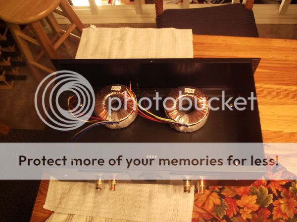
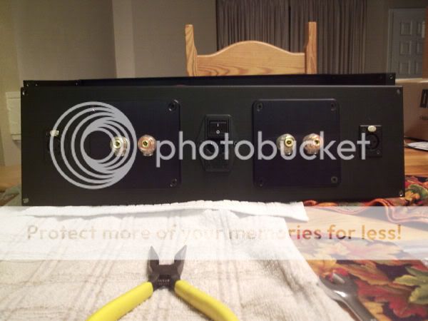
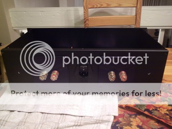
Day 1: I decided to work on the mechanical work first. Chassis is assembled, binding posts and IEC module are mounted. Pilot holes for the XLR drilled. I need to find a 13/16" bit to drill the final XLR jack holes. I can't find a bit this size locally  For reference those are 250VA toroids.
--Chris
For reference those are 250VA toroids.
An externally hosted image should be here but it was not working when we last tested it.
--Chris
Looks nice. Lately I have been making some pretty neat and professional looking holes in all thicknesses of alu up to 1" using my 'wood' forstner bits! They need a pilot hole 'cause the guide tip won't cut alu but they work real nice... I've been chucking them up in my drnll press at whatever speed I normally use for metal, give good firm even pressure and lube it well to keep it cutting and cool (wd40 has worked fr me). I have done 1/2" alu and ended up with a single 6 foot curled shaving representative of the metal that was removed. The only problem is that at the very end of the cut it ends up punching a very thin 'disk' of alu at the end. Run it 'good' side up and clamp the work down 'cause if it catches your going to get hurt. Don't ask how I know! It looks like a Bridgeport did it....
There's a special bit you can get at Home Depot or any other like
store for drilling larger diameter holes... the make i have is an
Irwin Unibit. It allows you to drill many different diameter
holes with one bit.
it's shaped like a cone, the deeper you drill the larger the diameter of the hole.
In fact, just do a search for Unibit and you'll find a pic of it
store for drilling larger diameter holes... the make i have is an
Irwin Unibit. It allows you to drill many different diameter
holes with one bit.
it's shaped like a cone, the deeper you drill the larger the diameter of the hole.
In fact, just do a search for Unibit and you'll find a pic of it
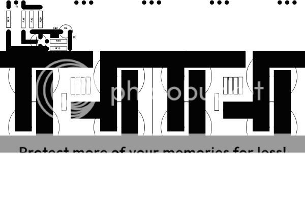
Day 2 Update: I think it counts as day 2 since its 2:15 am ... My local Lowes has one of those Unibits so I'll pick it up today. I laid out one of the power supplies. Comments on the layout apreciated.. I'll proably start working on one of the output channels tomorrow.

--Chris
... My local Lowes has one of those Unibits so I'll pick it up today. I laid out one of the power supplies. Comments on the layout apreciated.. I'll proably start working on one of the output channels tomorrow.
--Chris

Nelson Pass said:Ooooooh....Nice.
Thank you sir, It is an honor that you approve of my humble copy
A question. I used 1/2" traces for the Power supply. I plan to use 1/8" for all the current carrying paths in the channels and 1/16" for the low current paths. Are these sufficiently wide? I'm planning on using one sided 2oz copper PCB traces with a ground copper foil shield on the other side.
--Chris
steenoe said:That amp looks pretty good so far
Do you have plans for some kind of heatsink arrengement?
Steen
I'll be using thermaflow E1387 extrusions on both sides. at 100W they will be 34 degrees above ambiant. Just ordered these, will be a few weeks before I get them so I'm trying to get the PCBs done and the FETs matched in the meantime.
Details of parts/gathering materials can be found on this previous thread :
http://www.diyaudio.com/forums/showthread.php?s=&threadid=65483
--Chris
DIY_newbie said:
I'll be using thermaflow E1387 extrusions on both sides. at 100W they will be 34 degrees above ambiant. --Chris
Chris, summertime in Dallas would kill your F1 at 34deg above ambient...
Blues said:
Chris, summertime in Dallas would kill your F1 at 34deg above ambient...
34C over ambient is only 60C total.. The IRFP240s are rated to run 12A continuous at 100C... Am I'm missing something?
No comments on the trace widths I plan on using??
--Chris
Here's the scoop on the heat.
Your ambient is 80 F = about 25C. The "34 above ambient" means
that the fins will be 34 above ambient. So the fins are gonna be
59C. Like Blues said. That's hot. Too hot to hold your hand on
for more than a second. In the winter, if you keep your pad at
70F, subtract about 6C from all the numbers you calc.
The rest of the story is that there will be a delta T getting
from the transistor contact to the fins, a contact delta T,
and a delta T from the die to the contact. You can figure out
what these all are from the datasheet. Look for "theta J's" and
calculate for the power that each transistor is dissipating.
The above is an analog to a simple resistive circuit with a bunch
of resistors in series.
Here's a thermal sim for my amps:
http://www.passdiy.com/images/aleph gallery/a2-p1-f3.gif
And that's for the Aleph 2. I calculated that the junction temps
would be just shy of 95C. I think they are actually cooler than
that - maybe 90 or so - this based on the fact that the fins are
cooler than the sim predicted. Yours will be OK. But they will
get hot. Oh ya, I used silpads for heat transfer. Buck a pop.
FLAME ON !!!!
W
Day3: Dang, I knew I forgot to order something, Now I have to add SilPads to my list. Are the pads better than thermal grease? I finished laying out one of the constant current sources. I left a channel below each of th resistors that allows routing of the drain in either direction. I should be able to re-use this layout for the other current source this way. I have an alternate layout with the BJT moved to make it more symetrical. I plan to order the FETS : Q1,Q3,Q7,Q4,Q2 or Q3,Q1,Q7,Q2,Q4. Depending on how much room I have for routing. I'll layout the +input stage next...
Comments welcome...
--Chris
Comments welcome...
--Chris
Couple quick ones. OK three:
The silpads are better thermally than grease. Easier to work with too.
You would be well advised to use a thermal via like Chris Owen
suggests.
I'd advise not to try to use the anodizing layer as an electircal
insulator. But the transistors being used are already isolated,
the package back is plastic so in this case it doesn't matter.
W.
Im confused a bit here, are we talking about the same thermal grease? That is a say a tiny amount of grease that is used to fill any air voids between the package and heatsink. I thought that provided the best thermal contact, though no electrical isolation or convenience.
A quick update.
I've laid out the 2 p-channel current sources and one of the input stages. I'm having a little problem with routing to the bottom N-channel current source so I think I'll have to move things around again No pics with this update, but I should be posting the first pass at the whole amplifier channel in the next few days.. Its starting to look like a real amplifier
--Chris
I've laid out the 2 p-channel current sources and one of the input stages. I'm having a little problem with routing to the bottom N-channel current source so I think I'll have to move things around again
No pics with this update, but I should be posting the first pass at the whole amplifier channel in the next few days.. Its starting to look like a real amplifier --Chris
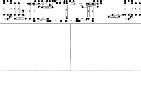
I've been real busy working on school these last few weeks, but I've finally finished the left channel layout.. I had to run some resistors at angles over each other to make it all work with a single layer board. Is this ok? Will this cause any kind of problems?
Layout :
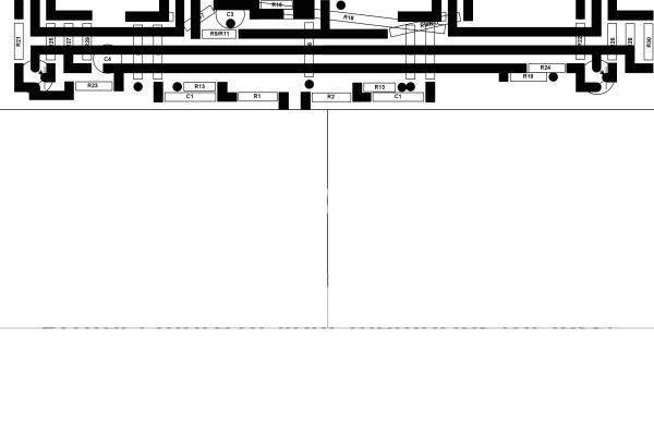
Drill/Population only
--Chris
Layout :
Drill/Population only
--Chris
- Status
- This old topic is closed. If you want to reopen this topic, contact a moderator using the "Report Post" button.
- Home
- Amplifiers
- Pass Labs
- First Watt F1 Construction Diary [pics]