Hi guys,
I've been hanging around here for same time, trying to figure out (as a non EE and almost a newbee) how to implement a x-feedback to folded cascode topology (like in Nelson patent), as it seems that folded cascode sounds superior to other design if done correctly. N. Pass, C. Hensen and J. Carr (to name a few) use it with great succes, Analog Devices uses it in their opamps which sound and measure excelent. So I first try to convert a A75 input stage/ folded cascode (as preamp) to use x-feedback, but I have no luck/knowledge to succed there. Then, I try with Ayre schematic, and it seems that I finally have some luck .
.
Q: is it a x-feedback or not?
I've been hanging around here for same time, trying to figure out (as a non EE and almost a newbee) how to implement a x-feedback to folded cascode topology (like in Nelson patent), as it seems that folded cascode sounds superior to other design if done correctly. N. Pass, C. Hensen and J. Carr (to name a few) use it with great succes, Analog Devices uses it in their opamps which sound and measure excelent. So I first try to convert a A75 input stage/ folded cascode (as preamp) to use x-feedback, but I have no luck/knowledge to succed there. Then, I try with Ayre schematic, and it seems that I finally have some luck
.Q: is it a x-feedback or not?
Attachments
Well, what can I say, thank you very much Nelson and others heroes around here. Without your help I'll be nowhere.
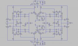
During my regular work today, I have some spare time to figure out how to implement x-feedback around A75 folded cascode driver. As is explained in service manual, one may choose how to wrap around negative feedback: from folded cascode drains only, from +/- output only and from both as in new schematic. Your choise, works great in sim whatever you deside to do. Or one my choose folded cascode or regular cascode operation as writen in service manual.
I have noticed that output impendace goes up for about 100% (from 0,75 to 1,5 Ohm) when mix feedback is used. I know there is nothing to worry about, but I would like to know why is that, 'couse I would expect to go down?
Best, a
Attachments
Hi, aparatusonitus
R50 (1meg) and C18 (1u) are forming low pass filter?
What is the advantage of having M9,10,11,12 referenced to the output stage, compared if they are referenced to solid reference (like zener or R divider between ground and rail, not towards output node)?
R50 (1meg) and C18 (1u) are forming low pass filter?
What is the advantage of having M9,10,11,12 referenced to the output stage, compared if they are referenced to solid reference (like zener or R divider between ground and rail, not towards output node)?
lumanauw said:R50 (1meg) and C18 (1u) are forming low pass filter?
I think they are forming a high pass filter, at least thats what my sim shows.
lumanauw said:What is the advantage of having M9,10,11,12 referenced to the output stage, compared if they are referenced to solid reference (like zener or R divider between ground and rail, not towards output node)?
For one thing, you get full control over absolute and relative output DC offset thru potentiometers U1-4 (in sim I can get zero offset easily), not shure about others benefits or shortcomings.
Best,a

 ) Plassche Current Differential Amp as a load on a folded cascode LTP?
 What I need now is a little push guys
Originally posted by Nelson Pass Well, it's certainly different
Well, that's me...
Originally posted by Nelson Pass but I have no intuition as to how well it will work.
I guess you meen work at all or...
Nelson Pass said:I didn't mean to imply that. Usually when I see a circuit, I've
been there, so I can say "That's great" or "That sucks", but
in this case I can't fall back on experience and this circuit is
more complex than I have time to analyze in any kind of depth.
During my regular work today
 I suddenly figured out what is wrong: it's all about feedback. It's working flawlessly now .
Now, I can say to my son (which I don't have) one day: I have beat Nelson, I got there first
Now, could you find some time please (in future) and explaine as (me) what I have just done?
Attachments
aparatusonitus said:Now, could you find some time please (in future) and explaine as (me) what I have just done?
Not too easy to say. The unique part is in the input stage.
Since it is symmetric from plus to minus, I'll just discuss the
negative half, transistors M25-30.
25 and 26 are followers, driving the sources of 27 and 28.
27 and 28 are cascodes and then off to the output stage.
29 and 30 are used to bias 27 and 28 and their Drains would
be intended as the communication point between the left
and right halves of the circuit.
After the Drains of 27 and 28, the circuit is similar to others
that have been drawn.
It looks to me like the circuit is non-inverting, so it would have
positive feedback as shown. I think first you need to reverse
the feedback connections. Then I think (offhand) it will work,
but I don't know how well. No doubt you will have to do a
good job matching M25-30 and their positive half counterparts.
Thanks Nelson for your time and explanation, I can understand circuit much better now. As shown below, circuit is inverting now with change in feedback points. Distortion at 1kHz are very good, but at 10kHz things are pretty bed. My sim shows me that I have severe distortion on inputs as well on outputs, but one thing is interesting, I got lower distortion on outputs then on inputs. So, is it means that feedback is doing its job as intented?
Attachments
- Status
- This old topic is closed. If you want to reopen this topic, contact a moderator using the "Report Post" button.
- Home
- Amplifiers
- Pass Labs
- Ayre style X-Preamp?