Stabist said:As I understood: it is better to replace with pot only R11
If you are concerned with the signal path, yes R11 trimpot is a better choice.
Banned
Joined 2002
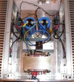
Here is my mini a up and running.. Both channels are running but here is a pic of one..
http://jleaman.ath.cx/dac/IMG_2314.JPG
Feel free to see my photo's ( taken at night )
http://jleaman.ath.cx/dac/
http://jleaman.ath.cx/dac/IMG_2314.JPG
Feel free to see my photo's ( taken at night )
http://jleaman.ath.cx/dac/
Zdravo chip,
First about nick - yep it does - I own Stabi2/Stogi Ref combination and I quite like it ... And so this was an idea for nick ...
AHA - now the things become cleare a bit ...
Altough - shouldn't the math for that additional parallel resistance be like - I want to have 25,6mA - and I have 5,5V drop - so resistance is 215R - and yes - by adding 6k8 in parallel to 221R - you get something like that ...
As said before - the problem with mosfet matching is:
- those were purchased as allready matched - and I expected them to be so ... But OK - if not so - I'll just have to deal with them on my own ... Fortunately recently I purchased 50pcs (whole lot) of them - so there must be enough pairs for my all futur Aleph related projects in that lot")
The thing that worries me more is - I also bought 14 "matched" output transistors - 12 for A30 and 2 for reserve ... BUT if they are also so badly matched as those 9610 - then I guess I'll have problems with building my A30 with them( And to buy 25 or 50pcs of 240 is much more expencive than with 9610 ...
Well we'll see ...
Pozdrav
First about nick - yep it does - I own Stabi2/Stogi Ref combination and I quite like it ... And so this was an idea for nick ...
AHA - now the things become cleare a bit ...
Altough - shouldn't the math for that additional parallel resistance be like - I want to have 25,6mA - and I have 5,5V drop - so resistance is 215R - and yes - by adding 6k8 in parallel to 221R - you get something like that ...
As said before - the problem with mosfet matching is:
- those were purchased as allready matched - and I expected them to be so ... But OK - if not so - I'll just have to deal with them on my own ... Fortunately recently I purchased 50pcs (whole lot) of them - so there must be enough pairs for my all futur Aleph related projects in that lot
The thing that worries me more is - I also bought 14 "matched" output transistors - 12 for A30 and 2 for reserve ... BUT if they are also so badly matched as those 9610 - then I guess I'll have problems with building my A30 with them
( And to buy 25 or 50pcs of 240 is much more expencive than with 9610 ... Well we'll see ...
Pozdrav
Blues said:chip_mk, if I got your explanation right...Stabist can also either tune his Aleph DC offset by replacing R11 or R14 with a trimpot say 500ohms. He can either tune with R11 so as he can have double the current through R14 or he can tune R14 to have half of the total current through R11. He can best tune either way by monitoring DC offset at the output.
Hi Blues
When equal current flows through Q1 and Q2 the pair works in its most linear part of the transfer curve and has highest amplification (transconductanse). However, this doesn't necessarily coincide with zero DC offset at the output. You can have it both only if the pair is well matched. Otherwise you either have well set input stage but some DC offset or zero DC offset but somewhat reduced performance of the input stage (or you make a compromise). That's why the matching is so important (although NP reported that in some cases not so well balanced input stage sounds good).
My suggestion was to use R11 for trimming in order to get optimal polarization of the input diff pair (symmetric current flow) and/or output DC offset. If you want to trim R11 use a serial connection of fixed resistor and a trim pot to provide +/- 20% trimming.
BR
Chip
Stabist said:As I understood: it is better to replace with pot only R11
Hi Stabist
My point is that in most cases DC offset can be adjusted by slight trim of R11 (+/- 20%). Of course, matching of Q1 and Q2 should be as good as possible. I don't recommend simple replacement of R11 with trim pot since accidental turn to 0 ohm can damage the amp. Instead you can use serial combination of 180E resistor + trim pot of 100E.
However, since you have provided measured values (24.8mA via Q3 and 12.8mA via Q1) I was able to calculate that instead messing with trim pot you can achieve decent correction simply by putting 6k8 resistor in parallel to the existing R11 (which is 220E).
BR
Chip
Hi Chip - I refered to idea of Blues, that should both (R11 and R14) have the option to be variable - and as understod your good explanation - I think it is not necessary to to do that with R14 at all ... Because changing R14 has bigger "side effects" than changing value of R11 ...
Chip,
Can you recommend a trim pot (in series with R11)? A typical trim pot resistance value that would work with any of the Aleph amps. What I meant is can you provide a PART NUMBER and a VENDOR NAME? I would like to put this trim pot on my order list the next time I'm ordering something.
Can you recommend a trim pot (in series with R11)? A typical trim pot resistance value that would work with any of the Aleph amps. What I meant is can you provide a PART NUMBER and a VENDOR NAME? I would like to put this trim pot on my order list the next time I'm ordering something.
chip_mk said:
Hi Stabist
My point is that in most cases DC offset can be adjusted by slight trim of R11 (+/- 20%). Of course, matching of Q1 and Q2 should be as good as possible. I don't recommend simple replacement of R11 with trim pot since accidental turn to 0 ohm can damage the amp. Instead you can use serial combination of 180E resistor + trim pot of 100E.
However, since you have provided measured values (24.8mA via Q3 and 12.8mA via Q1) I was able to calculate that instead messing with trim pot you can achieve decent correction simply by putting 6k8 resistor in parallel to the existing R11 (which is 220E).
BR
Chip
Gee ... I guess it's really time to match a lot of my own 9610 and forget about those "matched" ones ...
After adding 6k8 in parallel - I've only improved DC offset for around 5mV - but it is still somewhere around 40mV ...
First I'll check also the right channel and see what the numbers there will say ...
After that - I'll see how to continue ...
Banned
Joined 2002
Stabist said:
Gee ... I guess it's really time to match a lot of my own 9610 and forget about those "matched" ones ...
After adding 6k8 in parallel - I've only improved DC offset for around 5mV - but it is still somewhere around 40mV ...
First I'll check also the right channel and see what the numbers there will say ...
After that - I'll see how to continue ...
Id have to say if yor fet's are not mached this is going to keep happening
Yep - time to match them on my own ...
Right channel even worse - aroun 50mV DC offset ...
All other numbers pretty much same for both channels - maybe just couple mV difference between channels ...
BTW - one Q about AC current ratio - if voltage drop on both source "power" resistors is same - is maybe that also an indicator of 50% ratio - and as "upper" resisitor goes to higher voltage than the other one - that means the ratio goes from 50 --> 100% or not??

Banned
Joined 2002
Nelson Pass said:This is a lot of excitement over an offset voltage well within
spec. I suggest you kick back with a nice glass of wine and
enjoy the result of your labors.
Tell you what - I'll bless it over the Internet.

Good Job Nelson
Nelson Pass said:This is a lot of excitement over an offset voltage well within
spec. I suggest you kick back with a nice glass of wine and
enjoy the result of your labors.
Tell you what - I'll bless it over the Internet.
Hi Nelson,
You're more than right - it's in my nature to do
 all the time
Now I must complete AlephL and than join them into same chassis and so get a nice integrated amp
which will  , I'm sure of that
 The thing that matters most is that the
 has now entered and another Aleph is born
 Btw - is my conclusion about measuring AC current ratio via voltages on source resistors correct?
Attachments
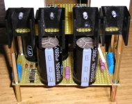
Stabist said:
Btw - is my conclusion about measuring AC current ratio via voltages on source resistors correct?
Hi Stabist
Identical voltage on Source resistors indicate that the output MOSFETs are well matched and are biased by equal currents. Since they are devices of the same type, the same manufacturer, probably the same batch, you can be sure they will exhibit the same AC (dynamic) performance.
Now I would like to correct what I've wrote in one of my previous postings. Adding a source resistor to some of the fets of the input pair in order to correct DC offset does not introduce asymmetry in the transfer curve of the input stage, at least not at lower frequencies when the impedance of the constant current source (Q3) is very high and ignorable. You said the current through Q2 is about 12mA, so adding a source resistor 3E3 to Q2 will reduce DC offset for about 40mV without worsening the current distribution. However, source resistors do decrease open loop gain of the amplifier and the loss would be more than 1/3 if you add the mentioned resistor. So matching is still the best way to go.
In mid '80s my neighbour used to own early Stabi platter with Grace tone arm and Supex pickup. I was about to buy Stabi in '87 but finilay decided I could not afford it. Anyway, my LP collection was/is pretty limited.
Lep(?) Pozdrav
Chip
- Status
- This old topic is closed. If you want to reopen this topic, contact a moderator using the "Report Post" button.
- Home
- Amplifiers
- Pass Labs
- 1 channel of MiniA working - measurments