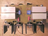
Aleph L finished  (it's done on the older version of AL schematic)
Measurments showed:
(btw - there isn't pot at the output right now but 10k resistor from out+ to GND)
Output PSU voltage: 53,1V (secondaries were only 1x50V)
- drop on R111:
L ch: 0,633V
R ch: 0,637V
- drop on Q103:
L ch: 4,2V
R ch: 4,2V
- drop on R107:
L ch: 4,2V
R ch: 4,2V
- drop on common Drain to GND: 33V
Hmm - all other measurment are pretty close to original schematic - excpet the last one - considering +53V PSU voltage - I would more expect something like 27V ...
Btw - the fets have around 45-50°C surface temperature - too much or not to worry about?
There are two changes to original schematic - one is lower PSU voltage and other one value of c104 - instead of 680pF 1000pF ...
(it's done on the older version of AL schematic)Measurments showed:
(btw - there isn't pot at the output right now but 10k resistor from out+ to GND)
Output PSU voltage: 53,1V (secondaries were only 1x50V)
- drop on R111:
L ch: 0,633V
R ch: 0,637V
- drop on Q103:
L ch: 4,2V
R ch: 4,2V
- drop on R107:
L ch: 4,2V
R ch: 4,2V
- drop on common Drain to GND: 33V
Hmm - all other measurment are pretty close to original schematic - excpet the last one - considering +53V PSU voltage - I would more expect something like 27V ...
Btw - the fets have around 45-50°C surface temperature - too much or not to worry about?
There are two changes to original schematic - one is lower PSU voltage and other one value of c104 - instead of 680pF 1000pF ...
Attachments
Hi Chip,
thanks again for this explanation ...
Btw - about those source resistors measurments - I was refering to this post by wuffwaff
That can be found here:
http://www.diyaudio.com/forums/showthread.php?s=&threadid=43890&perpage=10&highlight=&pagenumber=3
thanks again for this explanation ...
Btw - about those source resistors measurments - I was refering to this post by wuffwaff
Hi Kirc,
2.1A with 50% ac-current-gain should give around 50 watts 8 ohm (voltage limited) and 35 watts 4 ohm (current limited). (4.2A peak current)
25 watts 4 ohms means only 3.5A paek current or 1-2.1/3.5 = 40% ac-current-gain
To get 90 watts 4 ohms (if you want that) you must raise peak current to 6.7A. With 2.1A bias this means around 68% ac-current gain. .
To get this you must lower R21 until 68% of the ac current flow through the upper source resistors and 32% through the lower source resistors (at 10 watt 8 ohms for example)
Try something like 390 ohms for R21.
William
That can be found here:
http://www.diyaudio.com/forums/showthread.php?s=&threadid=43890&perpage=10&highlight=&pagenumber=3
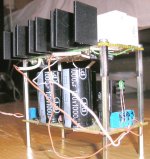
It will get a bit crowded at the back of the chassis ...
Trannie is "classical": EI; 120VA/2x12V + 40VA/2x25V
At around 1,35-1,4A bias/channel it works perfectly, doesn't produce hum, hasn't got any temp rises that would be worth to mention, etc ... With few words: EXCELLENT TRANNIE!!!
So now I'm not worried for bigger brother - A30 - for which I intend to use 2 pcs 160VA trannies from same manufacturer ...
I must still find a way to mount attenuator and selector switch somehow somewhere there at the back ...
Ofcourse - gretz bridge will NOT have his own heatsink but will be mounted directly to bottom ... So I will get some more place for capacitors placement and all ...
I'm still thinkig of a possibillitiy to use 4 of them instead od 2 - but then it will be REALLY crowdy
Attachments
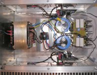
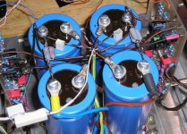
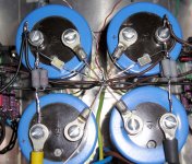
It worked and played but annoying buzz was there - and I've tried many different GND connections versions - but no significant succes ...
So obviously it was AC ripple ...
So I added another pair of capacitors + 0R16 resistance and so formed CRC filter ... (I will try to lower down resistance to somewhere around 0R1 - cause now I have almost 0,5V drop ... - but I haven't got enough resistors at hand right now)
AND it works without hum)))))
So obviously it was AC ripple ...
So I added another pair of capacitors + 0R16 resistance and so formed CRC filter ... (I will try to lower down resistance to somewhere around 0R1 - cause now I have almost 0,5V drop ... - but I haven't got enough resistors at hand right now)
AND it works without hum
)))))Attachments
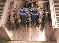
BUT now I have a bit higher bias current flowing through power resistor in "lower" half (between Source of the mosfet and -V) - on the "upper" one I can measure around 0,490V and on the "lower" one 0,536V (resisitors are 0R33) ... (same for both channels) ...
The voltage on PSU caps is same for (+) and (-) and completely simetrical ...
Also measured Voltage drop between (+V) and sense vs voltage from sense to (-V) differs for around 0,16V ... Before it was completely identical ...
What does that mean? Why suddenly thid change?
I also find DC offset a bit higher than before - before it was like 40 and 50mV - now it is like 60 and 70mV ...
now I have a bit higher bias current flowing through power resistor in "lower" half (between Source of the mosfet and -V) - on the "upper" one I can measure around 0,490V and on the "lower" one 0,536V (resisitors are 0R33) ... (same for both channels) ... The voltage on PSU caps is same for (+) and (-) and completely simetrical ...
Also measured Voltage drop between (+V) and sense vs voltage from sense to (-V) differs for around 0,16V ... Before it was completely identical ...
What does that mean? Why suddenly thid change?
I also find DC offset a bit higher than before - before it was like 40 and 50mV - now it is like 60 and 70mV ...
Attachments
Hehe ... "problem" solved
The thing was - because of hard acces to some parts of circuitry - I measured the voltage between one side of the resistor and -V on PSU capacitor - and after trying a bit harder I've manage to measure the votlage drop on both sides of the resistor after all - and YEP - now everything is OK)))
BUT then again - now I'm not quite satisfied while I have quite some voltage drop on the power supply cabling itself ... And hence that difference ...
Well, it's fun to giving a birth to that little chap))
Btw - it sings very nice Altough my ears says (but not mesaured yet) it starts to degrade the highs with raising the volume ... I guess I'll have to fidle a little with AC current gain a bit ... (that was allready in my plan before listening session) ...
The thing was - because of hard acces to some parts of circuitry - I measured the voltage between one side of the resistor and -V on PSU capacitor - and after trying a bit harder I've manage to measure the votlage drop on both sides of the resistor after all - and YEP - now everything is OK
)))BUT then again - now I'm not quite satisfied while I have quite some voltage drop on the power supply cabling itself ... And hence that difference ...
Well, it's fun to giving a birth to that little chap
))Btw - it sings very nice
Altough my ears says (but not mesaured yet) it starts to degrade the highs with raising the volume ... I guess I'll have to fidle a little with AC current gain a bit ... (that was allready in my plan before listening session) ...Banned
Joined 2002
Banned
Joined 2002
Banned
Joined 2002
jleaman said:Heck no.. Running 4 mini a's at full 1amp bias 1 stereo block per speaker connected bi-amp. Worknig great.. Of course they are still connected to the test speakers incase soemthign does happen
Mine operates at 1,5A bias and around 13,5-15V rails under load ... (this 1,5V volts of difference are the result of our house 230V is indeed very strictly within +/-10% - but unfortunately that also means during the day it "jumps" from around 210V to 250V
(( ) Well, I'll allready "switched" from test speakers to more serious ones - but still - I know perfectly what you mean ...
I still have some strange startups from time to time - when the amp gets full -V at speakers outputs
(( for few seconds In normal circumstances that is not the case - but I'm still not sure is it possible to get such possibly speaker damaging spike at some rare occasions (like AC 230V cut off for a moment - that's something that's quite "often" in our town)
Banned
Joined 2002
Yeah, I do use a termistor - but in particullary case when there is AC short term (0.xy sec) "shut down" - which is quite often in our neighbourhood --> termistor doesn't help much - it's still warm enough to have almost 0 resistance - so it isn't doing it's function ((
As said - I really don't get it what is the problem - same PCB - just used as a A5 - no problems at all ... This one - in majority works OK - but again and adain during test phase - from time time at powering on - it "sucks" the speaker membrane in and it stays there for few seconds (I guess it would - since I switch it off instantly) ...
--> termistor doesn't help much - it's still warm enough to have almost 0 resistance - so it isn't doing it's function ((As said - I really don't get it what is the problem - same PCB - just used as a A5 - no problems at all ... This one - in majority works OK - but again and adain during test phase - from time time at powering on - it "sucks" the speaker membrane in and it stays there for few seconds (I guess it would - since I switch it off instantly) ...
- Status
- This old topic is closed. If you want to reopen this topic, contact a moderator using the "Report Post" button.
- Home
- Amplifiers
- Pass Labs
- 1 channel of MiniA working - measurments