I got to thinking. . .
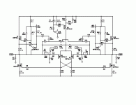
Well, I have always wondered if the current sensing resistors for an aleph amp were really necessary. I always wondered if there was a more elegant way to make an adjustable current source work. So I came up with this schematic. I'm sorry if someone else has already thought of this; I just didn't want to search through the forums for a few hours to find out.
Well, I hope it's self explanitory. R12 and 34 should be matched (or replaced with pots for current source gain adjustment) and R2 and 42 should be matched. VR4 would be used as a "coarse" current source gain adjustment. The values I haven't tried calculating yet. I'll get to that later. . .
Anyway, if R2 and R42 are small compared to VR4, a small difference in voltage would appear between the -output rail and C1; also between the +output rail and C6. (Just like in the original.) In which case the current source works exactly the same way.
Any thoughts?
Attachments
I have tried it, and you will note that the current output
is driven by the voltage differential, the result being that
it (theoretically) works perfectly if the load is resistive, but
does not respond to current which is out of phase with
voltage. As such, it's benefit is best suited to a lower
percentage of current gain than you might use with an
Aleph, say 20 to 30%, and then with known mostly resistive
loads.
OK, how 'bout this.
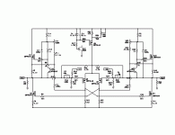
Nelson, after I posted the schematic, I thought there might be a problem with the design like what you described. So I backed up to an idea I actually had first, but seemed too good to be be true. So I'll go ahead a put it up also. Along with a philosophical point of view regarding the aleph current source.
By the way, you have probably tried this one too, and someone's probably already discussed it also. So I'm sorry in advance if this has been touched on before.
OK here we go. . .
In some of your other literature discussing the aleph, you tout the benefits of the "single ended" approach the aleph takes; you use an analogy of a violin bow controlled by one hand having more "finesse" than a bow controlled by two hands, one on each end. I am/was/still pretend to be a violinist, I studied and played 1st violin with the KU Symphony for 4 years. I get it, I can completely understand the benefits of a singled ended amp vs a push pull configuration, which I believe the analogy was supposed to represent, with a lack of "finesse" in the push pull due mostly to the unability to match N and P devices all that accurately. And you justify the "singled endedness" of the aleph (if I understand things right) even though it still uses two devices working in tandem (Q1 and Q2 in the original Aleph-X for example)
because the aleph current source (acting through Q1, reacts (through the voltage produced by the current sensing resistors) to the "single ended" amplification of Q2. This pairing of devices being beneficial over a push pull configuration mainly because Q1 and 2 are the same device, therefore able to be matched much more closely than push pull devices.
Whew, almost there.
But it seems to me, that because the aleph source is reactive in design, the end result is like adding another knuckle in the steering linkage in your car. That is, more "slop" or play in the steering; i.e. less finesse. Actually, I think I can make a good argument that the aleph current source is more like a 3rd gain stage than part of a 2nd gain stage.
Soooo. . .
Why not make the aleph source (Q1) controlled, through the miracle of su-sy, by the same signal as Q2. Ok, not the same signal, but its inverse. Like the schematic below. Which I believe avoids any problems related to the reactance of the load and brings the aleph source into "tighter" sync with the amplifying device.
I think.
Attachments
I think you could successfully make that. As an alternative
you could consider a JLH (or PLH) splitter. The point of the
Aleph is that the current source remains outside of the loop. It
operates in parallel as support to the output device. It is
not driven by the front end, rather, it is driven by sensing the
output current.
you could consider a JLH (or PLH) splitter. The point of the
Aleph is that the current source remains outside of the loop. It
operates in parallel as support to the output device. It is
not driven by the front end, rather, it is driven by sensing the
output current.
May I ask a question regarding the frequency response of the Aleph Current Source on its own ?
Is it right in saying that the bandwidth of the Aleph Current Source reduces with increasing load impedance of e.g. an Aleph or Alpeh-X circuit, due to an increased voltage change across Drain-Gate, thus increasing the effective Ciss of the MOSFET as seen by the collector resistor of the BJT ?
Thank you,
Patrick
EUVL said:Is it right in saying that the bandwidth of the Aleph Current Source reduces with increasing load impedance of e.g. an Aleph or Alpeh-X circuit, due to an increased voltage change across Drain-Gate, thus increasing the effective Ciss of the MOSFET as seen by the collector resistor of the BJT ?
Yes. The bandwidth is better at low impedances. Cgd is the
culprit at ordinary loads. At very low impedances the Cgs starts
being the limiting capacitance. It's not hard to increase the
bandwidth, but of course it will affect the overall stability of the
amplifier.
> It's not hard to increase the bandwidth,
Could you kindly drop a hint or two, other than e.g. using Cascode on the CS Mosfets ?
> but of course it will affect the overall stability of the amplifier.
My understanding is that if there is only one pole within the close loop bandwidth of the amplifier, then there cannot be much more than 90 degrees phase shift along the feedback loop, and the amplifier should be inherently stable.
The dominant pole, according to my undertsanding, is at the lower Mosfets driven by the diff pair, at some low kHz. So let's be greedy for now and set the close loop bandwidth of an Aleph-X 100W at 500kHz. If I could make sure I would get more than 500kHz closed loop bandwidth on the current source in itself, then there is no more elements in the loop to cause more phase shift, and I should not get instability ??
The problem is, if my calculations are correct, not at normal speaker impedances, but with no speakers connected (say 100 ohm from either output to ground) which causes the closed loop bandwidth of the Aleph current source to drop like hell due to Cgd & Miller effect. Which was why the original question in the first place ?
Perhaps I was thinking in the wrong direction and would appreciate someone pointing me back in the right direction.
Thanks in advance,
Patrick
As a practical matter, I have seen Alephs oscillate when the
bandwidth of the current source is dramatically increased,
whatever the cause.
To increase the current source bandwidth easily, you can first
increase the current going through the NPN bipolar device, and
decrease the gate resistor of the Mosfet, as well as the general
values of resistance in the rest of the network.
Also, you can use fewer Mosfets in parallel and/or choose lower
capacitance parts.
If that isn't fast enough, then you can cascode it.
Thanks for the replies and putting up with my "philosophical" rant.
I have been accused of thinking too much my whole life, and since nobody has accused me here yet, I might as well accuse myself!
Anyway, I think I'll try my second design soon, when I "finish" my Aleph-X's. I got my new transformers months ago but have been too lazy to swap them out and I still need to put front and rear panels on them. I think I'll add a switch to run them as either, CCS, ACS, or "my own homebrew ACS in the feedback loop design".
> As a practical matter, I have seen Alephs oscillate when the bandwidth of the current source is dramatically increased, whatever the cause.
Any possible explanations ?
I also had cases where I expected it to oscillate, and it didn't; or vice versa. So I am keen to understand it first before applying countermeasures.
And thanks for the advices in the previous posts.
Patrick
Any possible explanations ?
I also had cases where I expected it to oscillate, and it didn't; or vice versa. So I am keen to understand it first before applying countermeasures.
And thanks for the advices in the previous posts.
Patrick
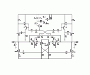
Well. I'm broke again, which means I have to start using my brain for fun, instead of money. So I got posessed with the idea designing an aleph-x that is switchable to class B. (My roommate is constantly turning off my amps as soon as I leave the house because I'm "wasting" energy. . .umm, whatever. . .)
First obstacle: making an adjustable current source from P-channel devices. Well check out the schematic. I've dubbed it the "Double-X" for now, for obvious reasons. I guess these really aren't even Aleph current sources, but their P-channel cousins.
Can anyone tell if this is a workable idea??? It seems that it is, but I need a little encouragement before I go any further, like tackling the second obstacle-biasing the devices to class B.
Any thoughts?
Attachments
- Status
- This old topic is closed. If you want to reopen this topic, contact a moderator using the "Report Post" button.
- Home
- Amplifiers
- Pass Labs
- A different Aleph-X