Dear pass,
I would like to operate the PLH at 28V, as I have 28V,4A regulated power supply. What are the changes needed in the circuit. Also I would like to operate this amp only in push-pull mode. Can I replace P2 with 390ohms + 110 ohms series connected resistors with the bootstrap capacitor connected at their junction?
Thanks
Routhun
I don't recall any mention of Xing the PLH. It could be done
if you restore the input transistor - more specifically, creating
a differential pair input.
With a more elaborate effort it could be done without the
diff pair input, setting up the negative output devices differentially
to create the same effect.

if you restore the input transistor - more specifically, creating
a differential pair input.
With a more elaborate effort it could be done without the
diff pair input, setting up the negative output devices differentially
to create the same effect.
Nelson Pass said:I don't recall any mention of Xing the PLH. It could be done
if you restore the input transistor - more specifically, creating
a differential pair input.
With a more elaborate effort it could be done without the
diff pair input, setting up the negative output devices differentially
to create the same effect.
Sorry for the confusion. I was asking about the direct coupled +- supply version of the PHL not an x'ed version.
Thanks!
I built one
A low powered one with 28V power supply and IRF630s in the output. It really sounds sweet and room filling. Since there is no thermal compensation you need very large heatsinks. I wish that I had a version without output capacitor. Hopefully Mr. Pass will find sometime to give us that version too.
Thanks,
Routhun
Would these fet's be a suitable replacement for the irf244
STW13NK60Z www.st.com/stonline/books/pdf/docs/8527.pdf
or maybe FQA44N10
sorry if thes are totally unsuitable, i'm not relly sure what the important charicteristics are apart from power dissapation, current, voltage ratings, and RDSon.
also has anyone come up with a split supply version?
STW13NK60Z www.st.com/stonline/books/pdf/docs/8527.pdf
or maybe FQA44N10
sorry if thes are totally unsuitable, i'm not relly sure what the important charicteristics are apart from power dissapation, current, voltage ratings, and RDSon.
also has anyone come up with a split supply version?
Orginally posted by gbullimore
also has anyone come up with a split supply version?
Could you please enlighten me why a split power supply is desirable? Please see post here for discussion about amplifier output capacitors.
It seems to me that a monopolar (single) power supply has the advantage of only one filter capacitor, the amplifier's output is not direct coupled to your loudspeaker (safety for your loudspeaker being toasted by an errant amplifier), and besides, your loudspeaker already has capacitors in the crossover, so you're not polluting something that isn't already polluted.
On the other side, the balanced Pass Aleph designs don't use a capacitor, and they made Stereophile Class A recommendations. There must be something to it.
does it make a difference that with a split supply you have the amplifiers PSRR 'between' the capacitor and the speaker?
does this make the capacitor quality less critical? than it would be if it was at the output?
i guess the ideal solution is to bridge the circuit and avoid the O/P coupling cap. does double the cost of the circuit though!
does this make the capacitor quality less critical? than it would be if it was at the output?
i guess the ideal solution is to bridge the circuit and avoid the O/P coupling cap. does double the cost of the circuit though!
The presumption of the split supply is that it eliminates the
output capacitor, although that can be accomplished with
single-supply balanced designs if you don't mind an absolute
DC (not differential DC) value at the output.
The PLH eliminated the input transistor which was the sole
provider of PSRR to the negative rail. This was not a problem
because the negative rail was ground. However with a split
supply the negative rail needs to be exceedingly quiet and
low impedance.
So practically you are stuck with an additional stage or the use
of an input transformer if you want to run split rails.
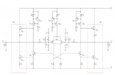
Here's my first try at a Balanced PLH. Something is incorrect. I'll look at it again over lunch.
Just for starters, each side uses 1A bias current at 50V, for a total dissipation of 100W. The power transistors are IRFP type, such as the IRFP044. The signal transistors are IRFD120/123, but the selection is mostly arbitrary. They are biased at 10mA each by a CCS running at 20mA (also an IRFD). I removed the discrete CCS and replaced it with an ideal source to make the schematic simpler.
The (-) input of the balanced pair connects to ground through the 10k feedback resistor and coupling capacitor. The (+) side is connected to an input signal.
Attachments
- Status
- This old topic is closed. If you want to reopen this topic, contact a moderator using the "Report Post" button.
- Home
- Amplifiers
- Pass Labs
- Plh