Hello
Zen V5 is very tempting for its simplicity
it is however represented very little on the forum
very few specimens are represented in the gallery
it is only one exercise?
presents it good quality?
which is the best supply voltage? (if there is one of them )
The ZV5 is much more sensitive to supply noise than other amplifiers : can a supply pi be appropriate? (CRCRC or CLCLC)
thank you for your opinions
Phill
In general, a CLC filter will be more effective and more efficient than a CRC. The CLC offers greater attenuation at high frequencies and (assuming that you're using large enough wire in the coil) very little loss. The problem is that inductors are more expensive and harder to find than resistors. Worse yet, they're physically big and heavy. With that in mind, a lot of people tend to go with resistors.
Resistors work well, just not as well as inductors. The power lost in the resistors can be offset if you start with a big enough transformer. You'll also have to provide sufficient ventillation for the heat given off by the resistors.
Adding on more sections, CLCLC instead of CLC, is a very effective way to improve the filter. It's just a question of money.
What rail voltage becomes a different question: How much power were you expecting to get out of the amplifier? You'll need to set a target wattage, then decide how much voltage will be required to meet that goal.
Grey
thank you GRollins
I will specify my question:
"The ZV5 is much more sensitive to supply noise than other amplifiers ==> Figure 8 shows the schematic of such a power supply. In many ways this is typical of the power supplies for the Zen amps, but it uses all the tricks to get low noise and low source impedance."
can I use a supply pi I have? or I must remake a complete sypply ? to be satisfied with this amplifier ...
I have just read again file pdf, it is very explicit !
in spite of my poor English level!
these amplifier one very little built : why ?
thanks
Phill
i built it.
The power supply isn't difficult to build... i wired it up point to point.
I haven't built the second channel yet, so i can't give you an opinion
on the sound quality... (shame on me) lol.
Go ahead and try it with a CLC... i'm sure as long as you have the
proper voltages it will work. For the best sound quality though,
i'd build the PSU as described in the article. I'm sure Mr. Pass put
some thought into it : )
good luck!
m.
If you already have a power supply on hand with reasonable voltage and current capability, why not try it? The worst that can happen is that it doesn't satisfy you, at which point you can simply go ahead and build another one.
As to why people build one circuit and not another, remember that Nelson published the original Zen article quite some time ago. The other Zens are much more recent. There simply hasn't been enough time for people to build thousands and thousands of them. As long as the design is sound, I wouldn't worry myself over how many units have been built. It's not a popularity contest, it's a quest to build a decent amplifier. If the circuit suits you, build it. Don't worry about what others are (or are not) doing.
Grey
GRollins said:If you already have a power supply on hand with reasonable voltage and current capability, why not try it? The worst that can happen is that it doesn't satisfy you, at which point you can simply go ahead and build another one.
If the circuit suits you, build it. Don't worry about what others are (or are not) doing.
Grey
your opinion seems to me very wise!
thank you very much
Phill
ingvar ahlberg said:Hi
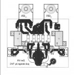
I´ve got a pcb design You can have if needed.
Ingvar
thank you for your contribution !
Phill
ZV5 regulated power supply
The Zen V5 regulated power supply uses two bridges: one for the positive and one for the negative supply voltage. It also uses complementary MOSFETs (IRFP240 and IRFP9240). While this looks pretty on a schematic, you could do it another way. You could keep the ground lines separate until after the regulating MOSFET (connect the negative terminal from one cap to the positive terminal of the other to create the ground reference) and duplicate the positive supply regulator with the IRFP240, or maybe even better, an IRFP044, for the negative supply regulator. The advantage is that both rails would use the same schematic and the same kind of MOSFET. Would there be any disadvantages? Would it be a problem that the ground line from the star point back to the transformer runs through a MOSFET and an inductor?
Comments?
Jeremy

There are no boards available from Pass Diy yet.
If there is enough interest out there i will get boards manufactured. High quality FR4 throughplated.
Theese will not be for sale but i´ll trade them for a record or a book or something else. If You´re passing throug this part of the
world ill regard´a good story and a cold beer as a fair deal too.
This is ,of course, provided i get an OK from NP.
Phill said:Zen V5 is very tempting for its simplicity
it is however represented very little on the forum
..
The ZV5 is much more sensitive to supply noise than other amplifiers
Zen V5
is an amplifier circuit I like
")
My own version of this topology might be a project for me
Amplifiers: Zen Variations - Part 5 by Nelson Pass (c) 2003
Attachments
- Status
- This old topic is closed. If you want to reopen this topic, contact a moderator using the "Report Post" button.
- Home
- Amplifiers
- Pass Labs
- Zen v5