someone ask for a schematic? this project went through many iterations ---
here's the unregulated version:
here's the unregulated version:
An externally hosted image should be here but it was not working when we last tested it.
Hi to everybody.
This is my first post, so.....
I know this is an old topic/tread but I have been looking for a solution to my problem(?) and cant find one.
I'm trying to match some mosfets and everything is going (or not) wrong.
I am following the instructions in the Passdiy webpage and the ones in here, but I still don't get the VGS between 3/4.6V my lower value is 0.842 and the higher is 1.120V.
My question is ... what am I doing wrong ?
My power supply is 18V and I'm using a 150 Ohms resistor the mosfets are the 2sj50/2sk135 (I have lots of them with same batch code).
Hope someone can light me up.
Rick
Grey is correct. 2SK135, etc are lateral FETs :
http://www.diyaudio.com/forums/showthread/t-19789.html
Your measured Vgs is normal. Please check datasheet.
Patrick
http://www.diyaudio.com/forums/showthread/t-19789.html
Your measured Vgs is normal. Please check datasheet.
Patrick
RS232 said:... but I still don't get the VGS between 3/4.6V my lower value is 0.842 and the higher is 1.120V.
My question is ... what am I doing wrong ?
My power supply is 18V and I'm using a 150 Ohms resistor the mosfets are the 2sj50/2sk135 (I have lots of them with same batch code).
Hope someone can light me up.
You are doing nothing wrong.
2SJ50/2SK135 has lower Vgs compared with IRFP.
I liked 2SJ50/2SK135 when I built my A/B class power amp.
As far as I remember, Goldmund also used them for their power amps . . .

Thanks thats good to know 
According to the datasheet for the 2sj50/2sk135 they have a Gate-Source cutoff voltage (VGSoff) 0.15 to 1.45V.
The ones I want to replace (IRF230/IRF9230) have a VGS from 2 to 4V.
Now I have another question
Can I use the 2sj50/2sk135 in one of the papas amps like the A75 or any other Aleph amps ?
Rick
We seem to have a lot of overlapping threads these days. There was just another thread where someone was putting lateral parts into an Aleph. The quick and easy answer is yes, you can use laterals in place of verticals in most cases. However, you will have to attend to the different bias requirements.
Grey
Grey
2SJ50 2SK135 Hitachi matching circuit
Hi , as being new in electronics I need a simple circuit to match a double pair of 2SJ50 / 2SK135 Hitachi mosfets for a 100watt amplifier.
Would it be difficult for "RS232" or someone else to draw the curcuit to show me the setup for matching output Hitachi mosfets?
Thanks for your cooperation in advance.
Gudmund
Hi to everybody.
This is my first post, so.....
I know this is an old topic/tread but I have been looking for a solution to my problem(?) and cant find one.
I'm trying to match some mosfets and everything is going (or not) wrong.
I am following the instructions in the Passdiy webpage and the ones in here, but I still don't get the VGS between 3/4.6V my lower value is 0.842 and the higher is 1.120V.
My question is ... what am I doing wrong ?
My power supply is 18V and I'm using a 150 Ohms resistor the mosfets are the 2sj50/2sk135 (I have lots of them with same batch code).
Hope someone can light me up.
Rick
Hi , as being new in electronics I need a simple circuit to match a double pair of 2SJ50 / 2SK135 Hitachi mosfets for a 100watt amplifier.
Would it be difficult for "RS232" or someone else to draw the curcuit to show me the setup for matching output Hitachi mosfets?
Thanks for your cooperation in advance.
Gudmund
How to match?
What do you suggest? It seems to me, without knowing, that it will be difficult to get the final result at operating voltage (approx 43Vac x 1,41 = 60Vdc) and Current approx 100mA per pair. Don't you think it will be sufficiant to messure on a woodboard at 15V and say: 170mA as I have seen Mr. Nelson Pass suggest. I have never seen the setup, and would like to have a drawing.
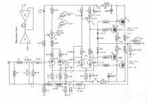
I wish to use a 1983 circuit which I owned back then, and liked the sound. Please find the circuit attached.
you have to make a decision:
do you want to match Vgs using operating current and voltage?
or
do you want to match Vgs at operating current and a low voltage?
The hardware for these two tests are quite different.
With To3 devices this is particularly so.
What do you suggest? It seems to me, without knowing, that it will be difficult to get the final result at operating voltage (approx 43Vac x 1,41 = 60Vdc) and Current approx 100mA per pair. Don't you think it will be sufficiant to messure on a woodboard at 15V and say: 170mA as I have seen Mr. Nelson Pass suggest. I have never seen the setup, and would like to have a drawing.
I wish to use a 1983 circuit which I owned back then, and liked the sound. Please find the circuit attached.
Attachments
Pass DIY Addict
Joined 2000
Paid Member
Gudmund, You might find some useful information on my Aleph-X web page. I have a whole section on matching mosfets...
Aleph-X 100w Amplifier Construction Notes
Aleph-X 100w Amplifier Construction Notes
Matching mosfets
Thanks Eric, just looked fast on the circuit for IRF fets. Could the old Hitachi's be used in the same circuit? ...and with the same voltage of 22vdc? ..at which amount of mA should the messurement be taken, to ensure them to be matched sufficiently for the attached power circuit?
Gudmund, You might find some useful information on my Aleph-X web page. I have a whole section on matching mosfets...
Aleph-X 100w Amplifier Construction Notes
Thanks Eric, just looked fast on the circuit for IRF fets. Could the old Hitachi's be used in the same circuit? ...and with the same voltage of 22vdc? ..at which amount of mA should the messurement be taken, to ensure them to be matched sufficiently for the attached power circuit?
Pass DIY Addict
Joined 2000
Paid Member
I'm not sure about the transistor substitution. In an ideal situation, you want to match your transistors at the voltage and current levels that they will see in the completed circuit. What I have discovered by playing around on my own, is that you can also achieve good matching at lower voltages and currents than the transistors will see in the completed circuit. Just keep an eye on the heat if using higher voltages and currents for matching. You might not be able to power them for more than 30-60 seconds before they get very hot.
Yes . but how?
Hi Hannes,
Yes ...but could you draw the setup for me. I have made the PCB in Cadint and the layout is checked.. the PCB is ready for mounting components. I have never used 2SJ50/2SK135 and have 10 of each ...hobe this is enough to get two matched pairs for each channel.
Rgds. Gudmund
Hi Gudmund,
from experience matching at about the same current but much reduced VDS gives good results. Just keep VDS above 5 V or so to safely stay out of the linear region.
Have fun, Hannes
Hi Hannes,
Yes ...but could you draw the setup for me. I have made the PCB in Cadint and the layout is checked.. the PCB is ready for mounting components. I have never used 2SJ50/2SK135 and have 10 of each ...hobe this is enough to get two matched pairs for each channel.
Rgds. Gudmund
Heat
Yes...I have some TO3 heatsinks for tests...I might need to mount them on a heatsink by use of a higher voltage. Which voltage would you suggest and the approx resistor value in the shown circuit on your site?
I'm not sure about the transistor substitution. In an ideal situation, you want to match your transistors at the voltage and current levels that they will see in the completed circuit. What I have discovered by playing around on my own, is that you can also achieve good matching at lower voltages and currents than the transistors will see in the completed circuit. Just keep an eye on the heat if using higher voltages and currents for matching. You might not be able to power them for more than 30-60 seconds before they get very hot.
Yes...I have some TO3 heatsinks for tests...I might need to mount them on a heatsink by use of a higher voltage. Which voltage would you suggest and the approx resistor value in the shown circuit on your site?
Pass DIY Addict
Joined 2000
Paid Member
Sorry, these details are missing from my web page - I'll update it shortly. Anyhow, I started with 22v rails and assume that the mosfets will drop 4v of power, so 22-4 = 18v. Then use Ohms Law (I=V/R) and plug in the voltage and current levels you wish to use for matching.
For me, I matched the bigger 240's at 22v and 1.125A. Plugging into Ohms Law, 1.125A= (22-4v)/ Resistor Value. Solving for R, you get R=V/I, or 18/1.125, or a 16 ohm resistor. For any other voltage and current combination, just plug in different numbers.
For me, I matched the bigger 240's at 22v and 1.125A. Plugging into Ohms Law, 1.125A= (22-4v)/ Resistor Value. Solving for R, you get R=V/I, or 18/1.125, or a 16 ohm resistor. For any other voltage and current combination, just plug in different numbers.
Sorry, these details are missing from my web page - I'll update it shortly. Anyhow, I started with 22v rails and assume that the mosfets will drop 4v of power, so 22-4 = 18v. Then use Ohms Law (I=V/R) and plug in the voltage and current levels you wish to use for matching.
For me, I matched the bigger 240's at 22v and 1.125A. Plugging into Ohms Law, 1.125A= (22-4v)/ Resistor Value. Solving for R, you get R=V/I, or 18/1.125, or a 16 ohm resistor. For any other voltage and current combination, just plug in different numbers.
Thanks...at your example we need P = I x I X R which gives:
1.125 x 1.125 x 16 Ohm = 20.25Watt ...a test resistor of at least 25Watt.
Did you only use this voltage/ampere and resistor value? ....I have one question more, and then I shall leave you alone.
The gate has a voltage value where the fet "opens". Is it nessesary to messure this voltage value to state whether the two fets is considered to be a good match? If so ...how do we messure this ? by a 10K multiturn pot from the 22Vdc supply to the gate?
- Status
- This old topic is closed. If you want to reopen this topic, contact a moderator using the "Report Post" button.
- Home
- Amplifiers
- Pass Labs
- Matching Mosfets