Thanks for the info, Ivo. Very clear and usefull information as allways") I think I will just leave the Riaa for BoZ as it is, for now. I have searched for suitable Jfets, but non of my usual suppliers have any. The "mosfet-hiss" is no big deal after all. With music on, it sounds great
I think I will just leave the Riaa for BoZ as it is, for now. I have searched for suitable Jfets, but non of my usual suppliers have any. The "mosfet-hiss" is no big deal after all. With music on, it sounds great
Steen
I think I will just leave the Riaa for BoZ as it is, for now. I have searched for suitable Jfets, but non of my usual suppliers have any. The "mosfet-hiss" is no big deal after all. With music on, it sounds great Steen
Hi Jürgen!
Please go ahead! If you can afford to buy some more pieces then it would be possible to select a proper pair of the highest (but preferably the same) gm.
To be honest with you, if have measured some IRF610 again and it turned out, that the gm@10mA is mostly in the range of 60mS. You will get this from a selected 2N6550.
Please note, that the bias voltage has to be altered from now 16V to 10.5V in order to maitain the operating point.
Ivo
Since it seems, I might get some of those 2n6550 devices, thanks to a nice guy around here I am jumping on the Jfet wagon again Looking forward to try that device. Would a setup like NP's in the article about mosfet testing be okay for selecting the devices? Or let me ask in another way, what is the best method for measuring the transcondutance in these devices? A schematic of a nice little test jig would be appreiciated
I second Jurgen, thanks a lot for your patience with us, Ivo.
Steen
I am jumping on the Jfet wagon again Looking forward to try that device. Would a setup like NP's in the article about mosfet testing be okay for selecting the devices? Or let me ask in another way, what is the best method for measuring the transcondutance in these devices? A schematic of a nice little test jig would be appreiciated I second Jurgen, thanks a lot for your patience with us, Ivo.
Steen
I can see no reason, why you couldn´t replace the IRF610 with an 2N6550 in the D1 circuit. But I wouldn´t.
In theory JFETs and MOSFETs work the same way. Since the Gate must be isolated from the channel, the only difference between those parts is the type of insulator. JFETs use a reverse biased pn-junction, whereas the MOSFET uses a SiO2 layer.
In the case of vertical devices second and higher order effects come in to action. All IR-types and the new Lovoltech JFETs are such devices. Second order effects can be nasty (IR p-channel types) or pleasant (triode characteristic of LU1016), but you can´t say a JFET is generally better than a MOSFET - it depends on application and device !
You can measure the transconductance dynamically (NP-paper) or with DC-voltages (see attachment). I find the static approach more convenient for selecting purposes.
Ivo
Attachments
finally finished my preamp, using teflon caps for the riaa. running the preamp off 2 sla batteries and using a meanwell switching psu as a charger. soundwise i'm impressed! sounds clean, noise floor higher but i can live with that!
Attachments
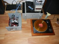
By the way, I hope you use a moving iron pickup with that phono stage. Having a big mosfet at the input brings a large loading capacitance (Cis) that will roll of the tremble of an ordinary MM (remember recommended loading capacitance of the manufacturer! Usually quite a bit smaller than the Cis of a regular power mosfet.).
Otherwise, enjoy! Hannes
hmm, I use a grado prestige gold mm cart, upgraded stylus, with no problems. this setup sounds far better than the commercial phono amps I've owned. almost matches my modified linn karik for sound quality. you could do a lot worse than a IRF610 when it comes to gate capacitance, the secret is proper biasing.
MOSeiden phono stage
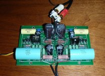
Built, playing now...
Sounds good, actually better than expected.
And less noise than expected too!
BUT, gain is a bit too low for my system, with passive/buffer-pre.
Maybe a single JFet in front would been perfect..?
( + another 6-10dB)
Arne K
Built, playing now...
Sounds good, actually better than expected.
And less noise than expected too!
BUT, gain is a bit too low for my system, with passive/buffer-pre.
Maybe a single JFet in front would been perfect..?
( + another 6-10dB)
Arne K
Attachments
Let's bump this again after some years!...
Hi all
1) I've not seen anyone comment on brands/types of capacitors recommended for this circuit - particularly in the riaa feedback network. I am considering these (but from a UK source) Vishay R. Film Caps
What do folk favour please?
2) What about the other components - any tips? Will use normal metal film Rs.
3) Also what is the expected current draw from the 24V supply - I reckon somewhere in the region of 60mA per channel?
4) Finally - those unusual resistor symbols for R102, R112 - diagonal stripe across one end. What do they mean - not found the answer on the 'Net?
Many thanks
Pete
- Status
- This old topic is closed. If you want to reopen this topic, contact a moderator using the "Report Post" button.
- Home
- Amplifiers
- Pass Labs
- Phono for Bride of Zen