.
.
.
Many manufacturers proudly show off the inside of their amplifiers (and other products). Mark Levinson, for ex, has a whole photo gallery of high res photos of both interiour and exteriour photos of all their products.
I have looked and looked to find some photos of Pass Labs interiour, but without any luck. Pass Labs show off their products' exteriour on their home page, but no interiour photos.
Does anyone have any photos of Pass Labs newer amps?
or maybe the wehereabouts of any photos?
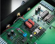
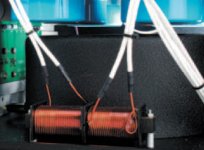
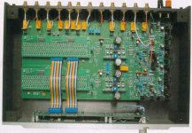
These two photos are from magazines, and they really show that Pass Labs has nothing to be ashamed off:
Regards,
Sigurd
.
.
Many manufacturers proudly show off the inside of their amplifiers (and other products). Mark Levinson, for ex, has a whole photo gallery of high res photos of both interiour and exteriour photos of all their products.
I have looked and looked to find some photos of Pass Labs interiour, but without any luck. Pass Labs show off their products' exteriour on their home page, but no interiour photos.
Does anyone have any photos of Pass Labs newer amps?
or maybe the wehereabouts of any photos?
These two photos are from magazines, and they really show that Pass Labs has nothing to be ashamed off:
An externally hosted image should be here but it was not working when we last tested it.
An externally hosted image should be here but it was not working when we last tested it.
Regards,
Sigurd
Big amp, small pic
An externally hosted image should be here but it was not working when we last tested it.
Banned
Joined 2002
have looked and looked to find some photos of Pass Labs interiour, but without any luck. Pass Labs show off their products' exteriour on their home page, but no interiour photos.
Thats because Nelson doesn't want Grey to reverse engineer the amps from just looking at the photos
 .
.Mark
You will note that I stayed out of the whole "let's reverse engineer the gain cell in the X preamp" thread. Showed remarkable restraint, I did.
As for reports of my untimely demise...they're exaggerated.
I've got the line stage I've been working on to a point where I'm content to let it sit for a while. I'll listen to it for a month or two and kinda let the whole project simmer; meditate on the whole thing. In the meantime, I'll retool my workbench for high voltages and get back to work on the Monster front end, a tube amp I promised a friend of mine ages ago, and have yet another fiddle with my crossover (which is currently tubed).
Grey
GRollins said:Showed remarkable restraint, I did.
Mmm, Turning into Yoda, he is..
I'm not sure efficiency is the term I would choose. Whether to place more capacitance on the initial or final leg of a PI filter is something that you can debate endlessly.
More capacitance on the initial leg will help smooth the pulses from the rectifier better. A small capacitor here will be depleted quickly by the circuit's current draw after the charging pulse has ended (and before the next one begins). This translates into increased ripple. The downside to placing the majority of the capacitance in the first leg of the PI is that a power amp can hit a peak and drain the final leg, decreasing dynamics and--in a worst case scenario--lead to the rail collapsing, which can increase distortion. Some circuits are unstable at decreased voltages, so you can get transient oscillations that are the very devil to track down, since they only happen for very brief periods of time. On the other hand, more capacitance on the final leg supports peak demand by the circuit better, but at the expense of greater ripple.
The solution, naturally, is to put huge amounts of capacitance everywhere. There are two problems here. One, obviously, is expense. Caps cost money. The other is that increasing the capacitance immediately after the rectifier (whether C, CRC, CLC, etc.) causes the caps to charge over shorter and shorter periods of time. The caps don't mind, but it's hell on the diodes to pass all the current required for the circuit over ever smaller fractions of a second.
Some people manage to work themselves into a lather about resonances in the filter circuit, but I've never had a problem along those lines, myself, nor do I know anyone who has. Theoretically it's possible. In the real world, it's just not worth losing sleep about.
I tend to put a moderate amount of capacitance after the rectifier, then a heavy bank after the R, L, or regulator. That's just my preference. I believe Nelson said in a post once that he preferred to go heavy on the first leg, but his views may have changed since then. If it's a vote you're looking for, most schematics I've seen show equal capacitance on either leg. If it's unequal, generally people lean towards more capacitance on the second leg, but there are plenty of exceptions.
The line stage I've been working on goes from the rectifier to a bank of caps, to a preregulator, to another bank of caps, through an umbilical (remote power supply), then another bank of caps (in the line stage itself), a second stage of regulation, and a final bank of caps before going to the circuit. The total capacitance for the line stage is greater that most amplifiers, something like 60-80,000 uF. Excessive? I guess. Maybe. Possibly.
But I humbled the owner of a CAT preamp this afternoon before coming to work. Something's working right.
Grey

If you dig deeper into the vast threads of diyAudio you will come
across other photos of Pass Labs goodness. I remember that
Peter posted some pics of an Aleph 0 from some German mag.
And there are some XA 200 pictures in the Aleph X thread that
Mr. Pass posted : ) There's pictures of an Aleph 3 that was highly
modified around here somewhere too. (very sacraligious!!) LOL.
I like to look inside my Aleph 3 for inspiration sometimes : )
GRollins, thanks for your detailed explanation. I see your points.
Nelson Pass, I already know you are a moderate father.
. . . only you . . . ? . . . hmm . . . I sometimes feel unequal amount love to my two sons . . . even if I never tell them as they never tell me who is better, mom or pa . . .
I had one cap of 22,000uF to each rail for my Monolithic SS.
But, lately, I changed it with 10,000/R/10,000/10,000 with a noticeable effect.
Why three caps? That time I had only three.
I bought one more of 10,000 days ago.
I want to add it. But, at front or behind . . . ?
. . . I will go to the front . . . with one thermistor at the entrance . . .
Once I saw XA100 and its . . . CCCCCCLCCCCCC . . .
Regards
jH
- Status
- This old topic is closed. If you want to reopen this topic, contact a moderator using the "Report Post" button.
- Home
- Amplifiers
- Pass Labs
- Photos of the inside of PASS LAB's Amps - Where?