I dare to restate a question already asked four days ago, but since there has been no reply, I take it that must have been overlooked...
1. The current draw through D1 - or, the optional 9 volt battery as I plan to use - anybody know what area this lies in - I suspect it to almost none, so that a 9 volt battery will last for years ?? Is it ok to use the same bettery for both channels - providing exact same reference for both channels??
2. the input load, in the article set to 47Kohms, is stated to be changed by applying resistors and capacitors across this resistor. Why capacitors - i se it as I can supply a switch with eg. another 47K resistor in parallel, and thus by flicking it, half the input impedance to 23,5Kohm, and so on ??
Thanx in advance !!
Cheers !
Hans Houmøller
Hi Hans")
1) I do not know, but the current draw is propably low. I use D1,
and it sounds good to me. If there is an advantage, using battery, I do not know about it.
2) Check your cartridge specs for the load needed. 47k is more or less the standard. Moving coil cartridges often have demands for a certain capacitive load. If you have a MC PU check the specs for the value. Most MM's dont need a capacitive load.
Dont forget the soldered wire from C15 to the GND solderpad!!!
The circuit says nothing, without it
Happy building
Steen
Edit, The voltages on Wayne's schematic are, I think just a guidance. I didn't measure the excact same values, still my Pearl sounds great
Hi Steen !
I will try to build it with D1 and measure - and then deside if I will include the battery
I did some work today, searching on pickups and turntables, and then I found out, as you write, that some pickups need capacitance...... its hard work to be a child of the CD, venturing out in the analog world for the first time........pheew !
I wil try and be calm and focused when woldering the circuit up, and dont forget any wire (like I always am when putting new toys together....NOT !)
What turntable and pickup do you use with it - have you any experience with the pearl and different pickups ??
Cheers !
Hans
I will try to build it with D1 and measure - and then deside if I will include the battery
I did some work today, searching on pickups and turntables, and then I found out, as you write, that some pickups need capacitance...... its hard work to be a child of the CD, venturing out in the analog world for the first time........pheew !
I wil try and be calm and focused when woldering the circuit up, and dont forget any wire
(like I always am when putting new toys together....NOT !)What turntable and pickup do you use with it - have you any experience with the pearl and different pickups ??
Cheers !
Hans
Hi Hans,
as far as I know you can only connect MD or high output moving coils to the pearl.
With MD you can tune the upper frequency range with input capacitance (something from 10 to 100pF). Input resistance should be left at 47k unöess you want to reduce the input signal.
With Moving Coils the input capacitance is of almost no importance. Input impedance will range from 20 Ohms to 47kOhms depending on make and coil impedance. With the moving coils I used over the years the influence of the input resistor was not very big and in some cases not noticable.
The curent through D1 can be calculated by looking at R5 and the voltage across it. 30V/3.32k= 9mA.
When connecting a battery I think you will have to take out R5. This way only the leakage current through the cap will flow wich should be near to nothing
William
I had an old, but in very good condition, Rega Planar3 from a friend. It has hardly ever playedWhat turntable and pickup do you use with it
Its the old model with an S-arm, wich is a bit on the heavy side, so I bought a Denon-DL110pickup thats made for a heavy arm, for it. I didn't want to spend too much money on the Grammo' thing if it didn't really catch on anyway
The DL-110 is a high-output MC. Sounds pretty good to me, but I am not sure this is my final PU Hmmm, I still remember the Grado Signature 6, I used to have......... William, you are right. I had them swapped in the previous post.With Moving Coils the input capacitance is of almost no importance.
Steen
Ground wire in pearl...
Steen - or anybody else for that matter - you wrote that a wire should be soldered C15 to the GND solderpad - should the C15 negative be soldered to the solderpad, and THEN to ground ?? On the PC board there's a line between these points, but should the wire continiue to star ground ??
Pheew, nothing beats when you can sit down with your soldering iron, and you have all the parts matched and ready at your hands - I feel like 10 years old on x-mas eve again, assembling a Lego kit !!!
Cheers !
Hans - with the first pearl channel almost finished....
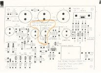
I have a drawing somewhere that shows the wire. Its a jumperwire on the PCB. There is a solderpad for it. I will dig up the drawing when I get a chance, and post again.should the C15 negative be soldered to the solderpad, and THEN to ground ??
Steen.
Isolated heatsink
OK - thanks for clearing that out Steen ! - and now another thing i hope you ( or someone else can help med with...)
I have not got any nylon screws for the heatsink for the 9610 FET, but the holes in the print that this sink is centered into, does not connect to grounds or anything else - I have "ohmed" everything with my multimeter, and cant find anything it connects to - can I safe use a metal screw - the drains of the FET is connected to the metal surface of the device, rigth ??
Cheers !
Hans
If you don't isolate the fet off from the heatsink, it will be electrically alive. Not that it matters for this circuit, but personally I dont like the idea of live heatsink's. Imagine what a screwdriver
or something can do by mistake
I did isolate the fet. VejleRC has cheap TO220 Isolation sets.
Look under: Reservedelslager\tilbud.
Steen.
or something can do by mistake
I did isolate the fet. VejleRC has cheap TO220 Isolation sets.
Look under: Reservedelslager\tilbud.
Steen.
- Status
- This old topic is closed. If you want to reopen this topic, contact a moderator using the "Report Post" button.
- Home
- Amplifiers
- Pass Labs
- Questions about Pearl.....