Check the TI web site
http://www-k.ext.ti.com/srvs/cgi-bin/webcgi.exe?Company={c7698c3f-af4f-4acc-bbc3-e615ef792d18},kb=analog,case=obj(32620),new
http://focus.ti.com/analog/docs/art...lifierdesignutilities_passive&articleType=brc
This should help you out
http://www-k.ext.ti.com/srvs/cgi-bin/webcgi.exe?Company={c7698c3f-af4f-4acc-bbc3-e615ef792d18},kb=analog,case=obj(32620),new
http://focus.ti.com/analog/docs/art...lifierdesignutilities_passive&articleType=brc
This should help you out
what kind of programmer do you have?
these informations could be found at the page i started to make some documentation for my PGA2310 volume controll
In university there is also a professional programmer avaiable, but i had no problems with the diy one from sprut.de until now.
in case you need only some for private usage i´m able to send them to you ready programmed.
http://home.arcor.de/dddddd-/PGA/index.html
I used the values as stated in Aleph L attenuator for the ouptut attenuators and the Goldpoint calculated values for the 10K input attenuators.
The attenuation has a very smooth action for the X Bosoz.
The 24 position Electroswitch referred to by Mr Pass works pefectly for both input and output.
macka")
The attenuation has a very smooth action for the X Bosoz.
The 24 position Electroswitch referred to by Mr Pass works pefectly for both input and output.
macka
Attachments
My passive, wireless remote control, battery powered preamp is coming! It should be puny in size & price compared to what I’ve seen so far in this topic.
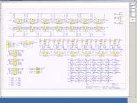
I'm now doing the IR receiver / processor & display PCB, schematic of the attenuator module is attached.
-It runs on 2 lithium coin cells. They should last at least a year.
-Consumption: 100ma for 2 seconds just after a volume change, 30ma for 3 more seconds while the 4-digit display is on, less than 0.003ma (3ua) while nothing is happening. Processor is completely stopped here, ABSOLUTELY NO EM signals being generated at this time. Even the microcontroller oscillator is shut down.
-Supply range, 5v to 16v dc.
-Supply is completely isolated from the analog audio path.
-Software selectable linear pot emulation, or, volumetric pot emulation.
-Software controls learns remote signals from 1 of your existing remotes.
-(modules only) Exclusive special price for DIYaudio forum members.
Everything should be ready in around 2-3 months:
ATTENUATOR MODULE:
-Fully passive. Break points at the ins & outs to allow for custom drive sections.
-Emulates 2 individual mono POTs allowing balance control.
-Selectable 100k, 50k, 25k, or 12k models.
-Super matching of channels, even when using all 16 channels.
-Encased in a copper shield.
-Fits vertically along the rear panel of a 1U rack-mount case leaving the rest of the case empty.
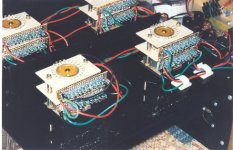
-Attached is a 128 step volume module with 6 line ins. It's finished.
-A 32 step, 3 line in econo module will also be available.
-Optional 0.1% resistors, or 0.5% resistors versions.
-1 module is stereo unbalanced, or mono balanced.
PROCESSOR MODULE:
-It will run up to 8 modules simultaneously. That's 16 unbalanced channels, or 8 balanced channels.
-Fits vertically along the front panel of a 1U rack-mount case leaving the rest of the case empty.
-Built in power supply regulation circuitry.
-Connects to attenuator modules via 1mm 6 pin flat flex cable, no other wires anywhere.
I'm now doing the IR receiver / processor & display PCB, schematic of the attenuator module is attached.
-It runs on 2 lithium coin cells. They should last at least a year.
-Consumption: 100ma for 2 seconds just after a volume change, 30ma for 3 more seconds while the 4-digit display is on, less than 0.003ma (3ua) while nothing is happening. Processor is completely stopped here, ABSOLUTELY NO EM signals being generated at this time. Even the microcontroller oscillator is shut down.
-Supply range, 5v to 16v dc.
-Supply is completely isolated from the analog audio path.
-Software selectable linear pot emulation, or, volumetric pot emulation.
-Software controls learns remote signals from 1 of your existing remotes.
-(modules only) Exclusive special price for DIYaudio forum members.
Everything should be ready in around 2-3 months:
ATTENUATOR MODULE:
-Fully passive. Break points at the ins & outs to allow for custom drive sections.
-Emulates 2 individual mono POTs allowing balance control.
-Selectable 100k, 50k, 25k, or 12k models.
-Super matching of channels, even when using all 16 channels.
-Encased in a copper shield.
-Fits vertically along the rear panel of a 1U rack-mount case leaving the rest of the case empty.
-Attached is a 128 step volume module with 6 line ins. It's finished.
-A 32 step, 3 line in econo module will also be available.
-Optional 0.1% resistors, or 0.5% resistors versions.
-1 module is stereo unbalanced, or mono balanced.
PROCESSOR MODULE:
-It will run up to 8 modules simultaneously. That's 16 unbalanced channels, or 8 balanced channels.
-Fits vertically along the front panel of a 1U rack-mount case leaving the rest of the case empty.
-Built in power supply regulation circuitry.
-Connects to attenuator modules via 1mm 6 pin flat flex cable, no other wires anywhere.
Attachments
I'm not supplying the gain stage, however, I left optional jumpers so you may add your own either right before the relay based pot, or right after depending on your preference.
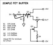
For a balanced system, I would recomend the bosoz design, for unbalanced & extra simple, I would use a simple JFET buffer. However, these do require a power supply. Since it's so small, I may just squeese it in without placing any of the parts.
Each attenuator module will have 4 line ins, it was originally 6. If you don't want my processor board, these modules have an I2C interface.
Attachments
Everything is now illustreted & explained here:
http://www.diyaudio.com/forums/showthread.php?goto=newpost&threadid=21159
http://www.diyaudio.com/forums/showthread.php?goto=newpost&threadid=21159
single-pot balanced volume control
Peter Daniel said in post #3 and #22 about the single-pot balanced volume control--
Please help my ignorance on the question of volume control impedance values.
1. How do you calculate the optimal value for a (normal) volume control at the input to your preamp? I have heard 25-50K mentioned for the BZLS input. How/why?
2. How do you calculate the optimal value for a (normal) volume control at the output to your preamp? I have heard 5-10K mentioned for the BZLS input. How/why?
3. With the single-pot method of volume control of a balanced amp, no part of the pot is grounded, or placed across the amp's input or output. How do you work out the right value for this pot?
Thanks,
Grant
Peter Daniel said in post #3 and #22 about the single-pot balanced volume control--
Instead of placing the pot between output and ground (4 needed) place the pot between positve and negative output of ea balanced channel (2 needed), so one stereo pot would work. This way, depending on impedance of the pot, positive and negative output will cancel each other without conecting to ground. You can find this setup in Pass D1 DAC.
Yes.I think it's better to do it after 221 resistors. Also 100k is too much for the output. Both this resistor's value and 5k to ground should be carefully chosen for best operation.
Please help my ignorance on the question of volume control impedance values.
1. How do you calculate the optimal value for a (normal) volume control at the input to your preamp? I have heard 25-50K mentioned for the BZLS input. How/why?
2. How do you calculate the optimal value for a (normal) volume control at the output to your preamp? I have heard 5-10K mentioned for the BZLS input. How/why?
3. With the single-pot method of volume control of a balanced amp, no part of the pot is grounded, or placed across the amp's input or output. How do you work out the right value for this pot?
Thanks,
Grant
Hi Grant,
The options to adjust the volume of the BZLS really freak you out, don't they? Apparently, the simplicity of the line-stage makes it more difficult to decide upon the 'right' level-control
Anyway here are my observations:
The maximum value of a pot at the input is restricted by the input capacitance of the MOSFETs. A high value pot together with this reasonable capacitance (in nano-farads) forms an RC-filter that causes a high frequency roll-off. For this reason, Nelson advices not to exceed 10k. In the Aleph P he just omitted the input pot to increase the bandwith of the line-stage.
The output impedance of the BZLS is directly related to the value of the pot. The lower the better and as Nelson explained 5k seems reasonable
I have simulated this alternative with Simetrix and found out that the value of the pot needs to be 1k to be effective. Be aware however that with unbalanced sources the output level of the two polarities of the signal is not the same, which makes the attenuation of the signal with a balanced attenuator a problem at low volume settings.
Hope this helps,
Fox
The options to adjust the volume of the BZLS really freak you out, don't they? Apparently, the simplicity of the line-stage makes it more difficult to decide upon the 'right' level-control
Anyway here are my observations:
1. How do you calculate the optimal value for a (normal) volume control at the input to your preamp? I have heard 25-50K mentioned for the BZLS input. How/why?
The maximum value of a pot at the input is restricted by the input capacitance of the MOSFETs. A high value pot together with this reasonable capacitance (in nano-farads) forms an RC-filter that causes a high frequency roll-off. For this reason, Nelson advices not to exceed 10k. In the Aleph P he just omitted the input pot to increase the bandwith of the line-stage.
2. How do you calculate the optimal value for a (normal) volume control at the output to your preamp? I have heard 5-10K mentioned for the BZLS input. How/why?
The output impedance of the BZLS is directly related to the value of the pot. The lower the better and as Nelson explained 5k seems reasonable
3. With the single-pot method of volume control of a balanced amp, no part of the pot is grounded, or placed across the amp's input or output. How do you work out the right value for this pot?
I have simulated this alternative with Simetrix and found out that the value of the pot needs to be 1k to be effective. Be aware however that with unbalanced sources the output level of the two polarities of the signal is not the same, which makes the attenuation of the signal with a balanced attenuator a problem at low volume settings.
Hope this helps,
Fox
3. With the single-pot method of volume control of a balanced amp, no part of the pot is grounded, or placed across the amp's input or output. How do you work out the right value for this pot?
I have simulated this alternative with Simetrix and found out that the value of the pot needs to be 1k to be effective.
1k!! That is extremely low. Why? What goes wrong with a higher value? The multi-channel volume control I am thinking of using only comes in 10k and larger sizes.
Grant
1k!! That is extremely low. Why? What goes wrong with a higher value? The multi-channel volume control I am thinking of using only comes in 10k and larger sizes.
Above 1k the signal won't be attenuated, which means that with a 10k-pot you can only use the first quarter of the pot-range. This results in a very small range to attenuate between very loud and very low sound pressure levels. Sorry but that's life for ya
Fox
Hi Laci,
I simulated the circuit at A (post 72) but contrary to the picture, after the 100K resistors. Attenuation before these resistors does not work.
According to my simulations, attenuation at the input (C) should work well with a 10k-pot. A 20k-pot should also work but does result in an increase of the signal in comparison to a 10k-pot. This implies that with a 20k-pot the range between 10k and 20k does not alter the signal level. So the conclusion seems justified that with a 10k-pot the most accurate level-attenuation is possible because the whole range of the pot can be used.
Hope this helps,
Fox
Hi, Fox,
Thanks for the explanations!
10 k much more fine for me. But, if you could, just one premium simulation: I suppose, the rule were to use log pots. Is this the only truth, or linear ones could be applicable, too? - eventually applying supplimentary items?
I think this alternative solution could be interesting for many diyers having lin pots in their drawers.
Regards,
Laci
Hi Laci,
Linear-pots can also be used. However, the attenuation will be heard in a counter-intuitve manner because the way we hear the difference between loud and less loud is on a logaritmic scale.
Somewehere I read that putting a resistor parallel to a linear pot results in a good aproximation of a logaritmic one. For instance, when you put a 20K resistor parallel to a 20k-pot, you would have a 10k-pot that behaves sort of logaritmic.
Good luck
Fox
Sorry to resurrect an old thread, but...
I'm having a big problem with putting the pot between the two lines of a balanced channel, as the simulation gives me an attenuation curve that is opposite from what audio taper is supposed to be. Most of the attenuation happens for pot settings that are lower than the series resistors it follows.
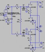
The attached image shows my situation; R4 is the pot, with the DAC output represented by the sources on the left, and the buffer on the right. Using a pot of just a few K gives a more normal curve, but the maximum volume is a third of the original, and with no voltage gain stages after this it's no good. I know there was a way to use a shunt resistor to fake a log law, but that does not work in this configuration. I can't figure out how to do this, so I hope someone can help.
I'm having a big problem with putting the pot between the two lines of a balanced channel, as the simulation gives me an attenuation curve that is opposite from what audio taper is supposed to be. Most of the attenuation happens for pot settings that are lower than the series resistors it follows.
The attached image shows my situation; R4 is the pot, with the DAC output represented by the sources on the left, and the buffer on the right. Using a pot of just a few K gives a more normal curve, but the maximum volume is a third of the original, and with no voltage gain stages after this it's no good. I know there was a way to use a shunt resistor to fake a log law, but that does not work in this configuration. I can't figure out how to do this, so I hope someone can help.
Attachments
- Status
- This old topic is closed. If you want to reopen this topic, contact a moderator using the "Report Post" button.
- Home
- Amplifiers
- Pass Labs
- balanced volume control