I compiled differents desings and added my own to create a nice little Soft Start and Standby circuit that can be usefull in building your Aleph.
Here the features:
The circuit is turn on by a main AC switch, possibly on the back of the amp then the softstart activate.
The softstart is the Elliot Project 39 version. A nice feature is that a small rating external switch can be used to turn on/off the amp from the front, it connects instead of a jumper on JP1.
Two nice additions are a safety feature of the soft start, a thermal cut off fuse, that will be mounted between the power resistors. It prevents any catastrophic failure.
The circuit can also power two 12Vdc fans. Their speed can be reduced by adjusting the value of R10. The Fans can be turn on/off automaticly by the standby mode or on continuously using JP2
Then working on the same 24V supply is the standby circuit. It is operated from a front mounted switch/led assembly or by remote 12V trig on the back. It provides these features:
-Auto-reset at start-up, standby mode activated, led inside power-on switch is flashing.
-Two DPDT relays can be used to provide the standby functions. I'm planning to short the inputs and select the lowest channel's bias setting in standby. The JP1 jumper can select the relays state in standby, On or Off.
-Press the SW1 switch, and the amp turn On full bias and ready. The SW1 led turn on continuously.
The momentary switch is well debounced and don't produce any false trigger.
-A 12V remote trigger on the back can activate the power-on mode remotely.
-A 12V alarm relay option. In case on an alarm inside the amp,
an external 12V will activate a rapidly flashing led.
The over-temperature cut off can be implemented using thermostat directly mounted on each channel heatsink, in serie with the main power switch and fuse, just before the soft start PCB. The digikey part number for the cut off is: 317-1085-ND
Thermostat, 75 DegC, Normally-Closed
Attachments
My idea for an Aleph soft start circuit is using an On-On switch, a two-color LED and a thermistor. The switch switches between supplying Vdc to the Aleph/LED or just the other color LED (at standby)...meaning it keeps the big caps charged as long as your main power switch is on. You'll need a higher value fuse for the initial surge...change it out to specs once caps have stabilized.
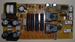
Yes. I tested. The prototype is working just fine since a week.
The IRF610 pinout is OK. I imported the case drawing from an other schematic. You're right, the IRF610 use TO-220AB. I'll do the correction.
Don't forget, this circuit was done for general purpose. I'll use it into other amps. Thermo Resistors, as used into the ALeph for surge protection are not working once they are hot. It means, that if you shut down the amp, then for any reasons you turn it back on, the surge protection is not there anymore and you can damage a rectifier bridge
I wanted also the possibility to remotely turn on the amp. I'll build a pair of Aleph-X mono blocks and I want to be able to start them from the preamp.
The newest PassLabs Serie use this scheme in standby, reduce the bias and short the input. This standby circuit do just that. In addition, the power on/led switch that I choose, was for its incredible look. It was momentary switch only and contain just one led. So I needed a circuit that can work with it
The Caps on the AC main voltages need to be specified for the main your using. Here they are 250, 275V for use on 120Vac. If you're using it on 230V, use at least 400V. Caps must be certified for use on AC main line, X2 type here in North America. I don't know the specs for Europe. Just proceed with caution, AC main is lethal
Anyway, it is a versatile little circuit. Use it if you like it or use some parts of it for inspiration.
I'll do a PCB desing on Eagle PCB. I'll post the PCB. I'm not planning to do a production run of it. Just feel free to do your own PCB. I do all my PCB myself. The real diy way
Have fun...
Maxhawk is in process of forming a GB for his softswitch. It looks pretty good.
http://www.diyaudio.com/forums/showthread.php?s=&threadid=61653
-David
http://www.diyaudio.com/forums/showthread.php?s=&threadid=61653
-David
hi,
great to see there is well build soft start board!
can you send me the high resolution file/Gerber?
Thanks in advance!
my email:
myip2004@yahoo.com.hk
great to see there is well build soft start board!
can you send me the high resolution file/Gerber?
Thanks in advance!
my email:
myip2004@yahoo.com.hk
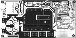
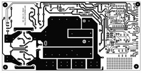
I've built the PCB (4 of them in fact) and it tested OK.
There is only a small change on the PCB. One of the AC power relays pin had to be insulated, and was not. Corrected the PCB, now version 1.01.
Corrected also a typo error on the schematic, U2 is 74LS04 and not 74LS14, it was ok in the parts list. Sorry for these errors.
Except for that, the PCB is working like a charm
Here the corrected schematic
Attachments
- Status
- This old topic is closed. If you want to reopen this topic, contact a moderator using the "Report Post" button.
- Home
- Amplifiers
- Pass Labs
- Soft Start and Standby Functions for your Aleph Amplifier