Dear all sir:
I'm fixing one pair of Threshold stasis 1 amplifier. Now it's normal working. But I don't know what is the bias adjust standard? I've searched some past thread and show it should set to 0.75A. But which point should I check to 0.75A? Or is any standard method to adjust the bias?
Sorry about my poor English.^^ Wish to find some answers.
Best Regarded!")
I'm fixing one pair of Threshold stasis 1 amplifier. Now it's normal working. But I don't know what is the bias adjust standard? I've searched some past thread and show it should set to 0.75A. But which point should I check to 0.75A? Or is any standard method to adjust the bias?
Sorry about my poor English.^^ Wish to find some answers.
Best Regarded!
Hi,
the ususal place is the fuse of the negative power rail. Remove the fuse and measure the current with your meter connected to the two connections of the fuse. But take care - it takes a long time until the reading gets to a stable status - even if you have removed the top plate of the amplifier housing.
Sorry for my bad english too.
cheers
Michael
Please, I need help.
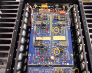
Here is the image of a threshold stasis 1 driver board.
There are 2 trimpot (those marked as 1 and 2) for bias regulation, one for positive and the other for negative rail.
I search the forum and I've found how to set them.
But i need to know how to set the 5 others trimpot (those marked 3, 4, 5, 6 and 7).
Wish to find some answers.
Best regards
Attachments
This appears to be a very early version - I was not aware that
there were any in the field. Unfortunately, I don't have a
schematic of this circuit, only the later, very different version.
Basically though, you have two amplifiers operating in parallel,
something that you can see if you go to the original patent.
One amplifier is the voltage amplifier, capable of delivering
current directly into the load, and the second is a current
bootstrap amplifier, which operates to source current to
the load which is a multiple of the current coming from the
original amplifier.
You can see the separate differential input pairs and the
offset and bias adjustments for each in the photo.
But i need to know how to set the 5 others trimpot (those marked 3, 4, 5, 6 and 7).
The pots which are not bias will be DC offset and gain balance
between the channels. If you think they need adjustment you
will need to monitor DC at the output of each amplifier and
locate the DC adjustments. Having identified the DC pots,
you adjust the remaining for minimal distortion in the
amplifier driving a load.
If you don't feel confident playing with this, then don't.
Thanks Mr Pass..
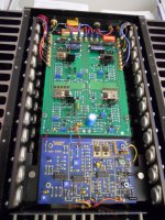
Unfortunately due to age of the original driver board, desolder and solder even using professional tools has damaged the tracks especially in the through hole pins.
Then I've rebuild the board itself. I attach the image... really it doesn't looks the same as the original gold and blue but now it's sounding really good.
Attachments
.....
Then I've rebuild the board itself. ......
respect for respect !

- Status
- This old topic is closed. If you want to reopen this topic, contact a moderator using the "Report Post" button.
- Home
- Amplifiers
- Pass Labs
- How to set the stasis 1 bias?