I know this is an old thread, but I recently picked up a pair of R 1.5s and was hoping someone could help out in regard to increasing the bias. How/where do I go about doing so (pot and/or replacing resistors?) Also, I presume by increasing the bias, the only ramification is increased heat, but the benefit is increased power in Class A, correct? Thanks in advance.
I would set the bias so that after a couple hours operation the
heat sink temperature settles into 50 deg C (ten second hand-
on-sink test)

pics , please
..... however how/where is it adjusted? Also, pics of ??
that's why I asked for pics (of amp opened) , to tell you where ....
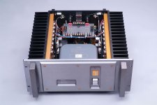
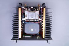
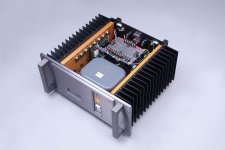
in a meantime , there are few I have
Attachments
Last edited:
Thanks very much, Zen Mod. My amps look very similar (terminal blocks on back side of cap board slightly different) but I do see 1 blue pot/channel. I'm concerned about adjusting the pots without A) a reference point as to where they are set now @ stock and B) Would like to be able to set both channels the same to ensure channel balance. I guess the best thing s to email Usher for service info....

that's not the way of linking or uploading pictures
in fact , it is , but your desktop isn't server , so ........
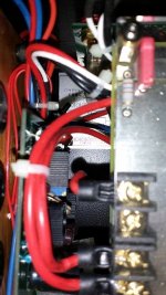
all you need is DVM put in mA range ; left red wire is most probably left channel + rail , while right red wire is most probably right channel + rail
then 50C as rule , while mA-meter to keep channels in same ballpark
Vmeter on output to confirm 0 offset , top lid in place between gradual steps of Iq increasing, to ensure temp equilibrium
as procedure example - several Treshold manuals , floating in recent Treshold threads
Last edited:
Reading a Threshold bias adjust procedure, looks like measuring voltage across an emitter resistor/channel is the recommended way to go. Is there any reason I should instead go with your method which I believe measures L and R difference of current across to ensure channel balance and also max temp @ heat sink at 50C?
Attachments
set Iq on one channel to have steady 50C on heatsink
go in little steps , iteratively !
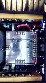
power off , connect ampermeter in PSU rail (disconnect red wire from pcb , connect ampermeter in series - back to pcb) , power on , write down what's Iq
power off , connect red wire back as it was
disconnect red wire of second channel , put ampermeter in series
power on , increase Iq in small steps iteratively , to have same current in temp equilibrium as already set in first channel
between adjusting steps top lid must be on amp case
check output offset on both channels , it must be lower than 50mV in temp. equilibrium , + or -
go in little steps , iteratively !
power off , connect ampermeter in PSU rail (disconnect red wire from pcb , connect ampermeter in series - back to pcb) , power on , write down what's Iq
power off , connect red wire back as it was
disconnect red wire of second channel , put ampermeter in series
power on , increase Iq in small steps iteratively , to have same current in temp equilibrium as already set in first channel
between adjusting steps top lid must be on amp case
check output offset on both channels , it must be lower than 50mV in temp. equilibrium , + or -
set Iq on one channel to have steady 50C on heatsink
go in little steps , iteratively !
power off , connect ampermeter in PSU rail (disconnect red wire from pcb , connect ampermeter in series - back to pcb) , power on , write down what's Iq
power off , connect red wire back as it was
disconnect red wire of second channel , put ampermeter in series
power on , increase Iq in small steps iteratively , to have same current in temp equilibrium as already set in first channel
between adjusting steps top lid must be on amp case
check output offset on both channels , it must be lower than 50mV in temp. equilibrium , + or -
Thanks Zen. A friend of mine has the R1.5 and while each of the two bias pots takes adjustment and the bias increase, the DC offset measured across the +/_ speaker outputs of each channel is very high. It is around 40mv for the left and around 90mv for the right. Is there a way to adjust the offset?
Another Appeal For Usher R1.5 Schematic.
Hi,
did you ever get a copy of this?
All the circuits posted here so far are not the same as the one I am trying to get going. Certainly not the Power Transistor layout.
I have had several Power Transistors fail with their associated Emitter Resistors and a couple of the Pre-Drive Transistors.
I have replaced the Pre-Drive and removed the Power Transistors leaving me with enough in there to run the thing on a low Voltage, Current Limited supply (+/-30V). It runs up and doesn't run away but is over driven on the negative side as opposed to the positive side (+0.9V/-1.8V) and produces distorted output above 2.8V pk-pk. This is of course all unloaded!
Any help from anyone would be appreciated, especially a correct schematic.
Thanks,
James.
Can someone provide me with the schematic of the R1.5 mk II
Hi,
did you ever get a copy of this?
All the circuits posted here so far are not the same as the one I am trying to get going. Certainly not the Power Transistor layout.
I have had several Power Transistors fail with their associated Emitter Resistors and a couple of the Pre-Drive Transistors.
I have replaced the Pre-Drive and removed the Power Transistors leaving me with enough in there to run the thing on a low Voltage, Current Limited supply (+/-30V). It runs up and doesn't run away but is over driven on the negative side as opposed to the positive side (+0.9V/-1.8V) and produces distorted output above 2.8V pk-pk. This is of course all unloaded!
Any help from anyone would be appreciated, especially a correct schematic.
Thanks,
James.
Hi Zen,
thanks for the reply.
Have found Q12 Collector/Emitter leaky, put a tempory replacement in there and the pre-drive stage now appears to be working. +/- 1.3V and a healthy looking signal (loaded the output of this PCB with Diodes to 'act' as the Output devices).
If the remaining Output devices are connected still produces fault conditions so suspect when I actually come to replace them I will find some which are leaky also.
Will get some on order, fit them and run up carefully (!).
Just one channel affected. However the construction of the Amp doesn't easily allow for a quick reference does it?!?!?
Thanks again,
James.
P.S. Still would like a circuit if someone can help.
All output transistors replaced and the associated 'Emitter' Resistors and all now is working as it should.
I had a working Channel so measured the Current Consumption of this when powered with a +/- 30V Supply and then set the repaired channel to this also.
Both channels get as warm as one another after 1/2 hours use so I am happy with this.
James.
I had a working Channel so measured the Current Consumption of this when powered with a +/- 30V Supply and then set the repaired channel to this also.
Both channels get as warm as one another after 1/2 hours use so I am happy with this.
James.
naah
without porn , we believe nuttin'

Pardon?

- Status
- This old topic is closed. If you want to reopen this topic, contact a moderator using the "Report Post" button.
- Home
- Amplifiers
- Pass Labs
- Are Usher amps just lookalike or buildt on licence?