Originally posted by zinsula
Doesn't BJT's keep the voltage at the emitter more constant than FET's while changing currents flowing through the devices?
That's the direction I was leaning towards. I had been thinking a standard cascode myself, but I see no reason at all not to go folded.
Cheer, Terry
Hi acaudio,
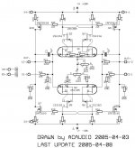
Your deleting of one of the adjustment pots gets back to my earlier post. The pots on the Pass Labs UGS are still a puzzle in my mind. The attached schematic fragment is not yet built and tested but it shows my best guess concerning the pots when I was working on the assumption that the Pass Labs UGS was based on Fig. 2 of 5,376,899. Since this is a folded cascode circuit the source degeneration was kept to a minmum by using 50 or 100 ohm pots.
NP has stated that on the Pass Labs UGS one pot adjusts absolute offset and the other adjusts differential offset. My intent was that adjusting the pots in the same direction adjusts one of these and adjusting them in opposite directions adjusts the other. Resistor R2 represents element 76 in the patent drawing and the value shown is from the patent text. It can be any reasonable value down to zero (highest gain).
In my schematic both pots adjust both factors symmetrically. NP implies that one pot does one thing and the other the other. On the other hand it could just be one of those semantic things......?
On another subject everyone should keep in mind that ideally there should be a place for the "MacMillan" resistors to attach to the UGS. These points are marked "B" on the X2 schematic (and on my schematic). The attachment needs to see the FET sources in a balanced way.
jam: Thank you for uli's schematic. Guests can't see the good stuff over on the other site.
Thanks to all. Comments welcome.
GL
Attachments
GL,
I guess you will have to become a member then................ .........you could see the evolution of the circuit.
Looking at your solution to adjust differential offset I suspect that both pots will interact with each other and hence you would have to go back and fourth between the pots to zero the offset.......just a hunch, but I could be wrong.
Jam
I guess you will have to become a member then................
.........you could see the evolution of the circuit.Looking at your solution to adjust differential offset I suspect that both pots will interact with each other and hence you would have to go back and fourth between the pots to zero the offset.......just a hunch, but I could be wrong.
Jam
jam said:GL,
I guess you will have to become a member then................
Looking at your solution to adjust differential offset I suspect that both pots will interact with each other and hence you would have to go back and fourth between the pots to zero the offset.......just a hunch, but I could be wrong.
Jam
Hi Jam,
You're right on both counts. First, I really should join and I have been intending to.
I think you're also right about the two pots, but I don't think you would need to go back and forth more than a couple of times to reach a final setting. To me this circuit does several things in a simple way and that appears to be worth the hassle of a certain amount of added tweekyness. Assuming the circuit works - which I don't yet.
GL
GL,
your version for adjustment should work, but the wide range of adjustment make (maybe) the circuit a little unstable.
The source resistors gives a local feedback to stabilize the bias point. Increasing the value decrease the gain ,input capacitance and noise. The common point between the both halfs should have a (virtual) ground potential. R22 (10K) pot in my last update helps here a little.
Cascode Friends,
The addition of cascode around 2SK389/2SJ109 with 2SK246/2SJ103 should give a again decreasing of input capacitance and THD, and gives a wider frequency range. Unfortunately, I haven´t actually the devices here to trying. See my cascode circuit. I´m very sure this would work pretty.
Grey,
you are right, we should use our intellect to find the right way and not only copying Mr.Pass circuits. We have to thank for his open mind and any help the he give us.
I´ll built a stereo version for first listening. I´m very curious for the sound and comparison with AP1.7. But my time is rare, work, family... are patient.
Regards
Adam
Attachments
Jeez, Mr. Rollins, we are not all capable of thatNelson says that the production ones are cascoded...but that doesn't mean that yours have to be. Jeez...does everything have to be a literal rendering of what Nelson does? Assert your independence--take an idea and build something different on purpose.
Still, many of us want a nice amp, like those Mr. Pass builds! So I guess many of the DIY'ers needs a road to follow No offence, whatsoever.
Steen.
To Everyone,
I think that one of the cool things about this thread is the diversity of circuit ideas. I would like to encourage people to keep this up. There are many ways to implement a Pass-like UGS and it would be particularly interesting to compare as many of these as possible.
On the other hand if NP has done something a certain way there's usually a reason and a good one. So what he has done should be considered valid as a starting point.
Regards,
GL
Originally posted by GRollins
Nelson says that the production ones are cascoded...but that doesn't mean that yours have to be. Jeez...does everything have to be a literal rendering of what Nelson does?
C'mon Grey, that's a pretty hypocritical statement coming from the man who backengineered the AlephX following Nelson's dropped breadcrumbs.
Nelson himself dropped the hint, so why is it so wrong to play with the idea and see where it goes? Also, I became a proponent of cascoding after hearing what it did for my BZLS. I would have suggested cascoding whether Nelson was using it or not just because I'm kinda fascinated by it at the moment.
All that being said, Grey, I personally value your continued participation in and contribution to this forum much more than my temporary interest in adding a cascode twist here, so I'll drop it.
Following breadcrumbs is much more fun than reading a
map.
More crumby hints:
The pots on the UGS are not the same, and are not arranged
symmetrically. No problem doing it another way.
The UGS is cascoded primarily because we wish to have the
circuit operate at higher voltages than allowed by the breakdown
voltages of the input JFETs. There is a slight performance
improvement that comes with cascoding, which is always
welcome.
map.
gl said:In my schematic both pots adjust both factors symmetrically. NP implies that one pot does one thing and the other the other. On the other hand it could just be one of those semantic things......?
More crumby hints:
The pots on the UGS are not the same, and are not arranged
symmetrically. No problem doing it another way.
The UGS is cascoded primarily because we wish to have the
circuit operate at higher voltages than allowed by the breakdown
voltages of the input JFETs. There is a slight performance
improvement that comes with cascoding, which is always
welcome.
Nelson Pass,
Speaking of Cascoding:
Example: JFet N for N and P for P
Is the "cascoding" JFet of same caracteristics as the original {cascoded}?
Are there general rules on this Cascoding subjest ???
Alain.
PS: Grey, excuses, but in my case: "I don't want the breadcrumbs ; I want the Cake" ; and it's always such a great pleasure to read Nelson's comments.
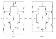
On the adjustment issue, I kept thinking last night about the adjustments on the AlephX, where absolute offset is primarily controlled by adjusting the differential pair's CCS. So I put the pot for adjusting absolute offset at the +ve rail where it feeds the top diff. pair, and put a resistor with half the pot value connecting the bottom diff. pair to the -ve rail. Except that does nothing for differential offset.
So I have been mulling today (to the detriment of my job performance), where and how to put a second pot to get the right effect, which is adjusting the current division between the two legs of the differential pair to vary the voltage output difference between the two sides. I came up with two ideas which are attached below. Just general concepts, I didn't bother to put in any input, output or feedback networks.
So I have been mulling today (to the detriment of my job performance), where and how to put a second pot to get the right effect, which is adjusting the current division between the two legs of the differential pair to vary the voltage output difference between the two sides. I came up with two ideas which are attached below. Just general concepts, I didn't bother to put in any input, output or feedback networks.
Attachments
Hi Cascodians,
NP has already provided information on how to add cascodes to input transistors. Look at files thr_fe89 and 90 in www.passlabs.com/np or the op-amp circuit of the Aleph Ono. My choice for the UGS would be to use MPSA42's (or similar) with the 2SK389 and MPSA92's (or similar) with the 2SJ109's. These should be biased with 7.5V zeners in order to have 6 - 7 volts across the fets. There are several examples of this on the web as well as in NP's work.
NP has stated previously on this web site that the JFET front end transistors in his X amps each run at 4 ma of bias current (in case anyone had missed that crumb).
Mr. Pass: Thank you once again for the crumby hints.
Regards,
GL
gl said:NP has stated previously on this web site that the JFET front end transistors in his X amps each run at 4 ma of bias current (in case anyone had missed that crumb).
this would give a low value of Rs (R1-R4 in my circuit) ~25 Ohm, hmm...

acaudio said:this would give a low value of Rs (R1-R4 in my circuit) ~25 Ohm, hmm...
From what I understand, the SUSY effect is better with not too high degeneration (=source resistors).
What dual 2SJ / 2SK IDSS ratings are you using? BL?
And, IDEA 2 seems very good to me. Will think about.
P.S:
I just saw the UGS4 picture out of a X250.5 in a magazine! Nelson, I see you are using the dual J-Fets. From what I know, they have been discontinued.
Did you buy the last truckload from those parts?

Happy DIY'ing
Ciao, Tino
zinsula said:What dual 2SJ / 2SK IDSS ratings are you using? BL?
Actually I use a mix 2SK389V +2SJ109BL, I looking for 389BL...,
but no problem... it works
Maybe I build the cascode version with 2x 2SK389 and 2x 2SJ109,
I have the components here, only for comparison. Supply +/- 30V should be enough.
Adam
Bricolo said:If you want to trade your 389V for my 389BL, contact me
I ordered already 389BL, thank you
Adam
- Status
- This old topic is closed. If you want to reopen this topic, contact a moderator using the "Report Post" button.
- Home
- Amplifiers
- Pass Labs
- X2_ugs3,4