Yes, it has started and I'm accepting payments for Aleph boards now.
I don't want to turn it into another group buy, that's why all the payments are done by contacting me personally. The price of one board (containing two Aleph channels) is USD$20 and includes all additional fees (shipping, packaging, handling), as well, any proceedings will be gladly donated to the support the forum fund")
Upon e-mailing me (with mail subject stated as A30 boards) I will provide paypal info, or other, alternative methods of payment can be discussed.
PS: I'm still working on a DAC offer, and it should be available soon as well.
I don't want to turn it into another group buy, that's why all the payments are done by contacting me personally. The price of one board (containing two Aleph channels) is USD$20 and includes all additional fees (shipping, packaging, handling), as well, any proceedings will be gladly donated to the support the forum fund
Upon e-mailing me (with mail subject stated as A30 boards) I will provide paypal info, or other, alternative methods of payment can be discussed.
PS: I'm still working on a DAC offer, and it should be available soon as well.
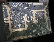
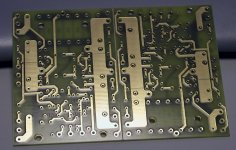
Peter Daniel said:So this is how it looks:
Boards look great! Can you put one next to a gainclone board, to provide an idea of the relative size? (separated would be good also)
--
Brian
Banned
Joined 2002
BrianGT said:
Boards look great! Can you put one next to a gainclone board, to provide an idea of the relative size? (separated would be good also)
--
Brian
Thanks, here how they compare, pretty close in size actually.
Attachments
I'm geting swamped with orders. For the info, this board is presently available. I ordered only 50 pcs. and it seems like I will be running short soon. This is not a problem and I can get another 100 made before the next Friday.
One board, containing two channels is $20, shipping and handling included (worldwide).
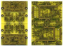
IMHO, this is a particularly good layout, and I have great expectations with regards to performance of this little (class A) amp. I will build the final version with Mills and Caddock resistors and Black Gates N type caps
One board, containing two channels is $20, shipping and handling included (worldwide).
IMHO, this is a particularly good layout, and I have great expectations with regards to performance of this little (class A) amp. I will build the final version with Mills and Caddock resistors and Black Gates N type caps
Banned
Joined 2002
Peter Daniel said:Will try to run some test tomorrow. The spread between devices is about right, and I don't imagine the heat dissipation could be a problem (with a right heatsink).
AH OH!! Jason likes that : O ) Wonder how big of heat sinks you need : O ) HUmmm.. now i should re-think my mini a's : O )
Peter Daniel said:
PS: Where is that guy who said the components are located without any particular order?
I'm here sweetheart.
I think I did play a part in pushing you to remove those few 'compromises' as you called them a few days ago. I still have a different vision for the whole think something with really-real short signal path.
I am looking forward to your measurements and listening tests, I seem to remember Brian interesting square wave ringdown findings when comparing his smd layout with the newer version.
Hopefully, you remembered to put the fuse and the zobel in this time.
The only concern I have is if input differencial can run without a heatsink.
I think they can, but one can always put a long and thin strap of copper in between them
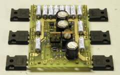
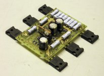
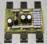
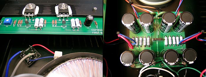
Somebody asked me if I will come up with a PS board. Well, personally, I don't see a need for such a board. Presented below (F1 amp) is a best example of an efficient implementation, so learn from the Master himself
All AC wiring is done p2p, with receptacle, fuse holder and power switch mounted directly to a rear panel. The bridges, attached to the bottom, don't need any extra heatsinking, and because bridges are used, wiring is very simple as well, so no need for additional PCB traces. The capacitor's bank, consisting of 4 caps per channel, can be easily mounted on protoboard, or any board for that matter, with heavy gauge wire undeneath creating connections. 5 resistors (I'm guessing 1ohm ea.) do the filtering, and those can be wired p2p as well. Worth noticing is that the PS output is not taken after the second caps bank, but directly after the resistors. This creates shorter and more efficient path.
More info here: http://www.6moons.com/audioreviews/firstwatt/firstwatt2.html

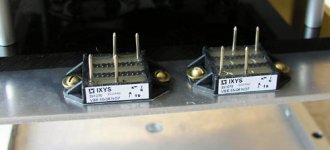
So by doing it in this way, you save your money by not paying for PCB, extra heatsinking, and shipping. That money could be invested into better bridges, like those IXYS available from Percyaudio.
All AC wiring is done p2p, with receptacle, fuse holder and power switch mounted directly to a rear panel. The bridges, attached to the bottom, don't need any extra heatsinking, and because bridges are used, wiring is very simple as well, so no need for additional PCB traces. The capacitor's bank, consisting of 4 caps per channel, can be easily mounted on protoboard, or any board for that matter, with heavy gauge wire undeneath creating connections. 5 resistors (I'm guessing 1ohm ea.) do the filtering, and those can be wired p2p as well. Worth noticing is that the PS output is not taken after the second caps bank, but directly after the resistors. This creates shorter and more efficient path.
More info here: http://www.6moons.com/audioreviews/firstwatt/firstwatt2.html
So by doing it in this way, you save your money by not paying for PCB, extra heatsinking, and shipping. That money could be invested into better bridges, like those IXYS available from Percyaudio.
Attachments
- Status
- This old topic is closed. If you want to reopen this topic, contact a moderator using the "Report Post" button.
- Home
- Amplifiers
- Pass Labs
- The Aleph30 PCB layout