Banned
Joined 2002

This weekend I'm building just one channel of the mini to prove the board. I will also provide some specs of the operating unit. In a week or so we may convert a friends Aleph 3 to a 30 with the other set of boards if time allows. I DO have to work also.....
What did you mean by regulated supplies in class A amps? The current source is actually modulated by the audio on the output.
Mark
What did you mean by regulated supplies in class A amps? The current source is actually modulated by the audio on the output.
Mark
Banned
Joined 2002
Cutting them apart is easy but very touchy as the thinest blade I had was a hacksaw blade. The bandsaw blade was way to thick to cut these boards. Pre-milling, perfing, or slitting these will be mandatory. Also, if you polish the tinning before you solder with 0000 steel wool the solder adheres very well. I use Kester Electronic Silver solder for everything I do here.
Mark
Mark
What did you mean by regulated supplies in class A amps?
What I mean is that the typical chip amp is built with an unregualted power supply. Transformed, rectified, capped and then on to the chip without regulation. The talk of regulation kind if disappeared after page 10 of this thread.
So, one more time...
Is it true of most class A amplifiers to be unregulated power supplies, or is it more common to regulate power?
Banned
Joined 2002
Mark A. Gulbrandsen said:Cutting them apart is easy but very touchy as the thinest blade I had was a hacksaw blade. The bandsaw blade was way to thick to cut these boards. Pre-milling, perfing, or slitting these will be mandatory. Also, if you polish the tinning before you solder with 0000 steel wool the solder adheres very well. I use Kester Electronic Silver solder for everything I do here.
Mark
I hope brian puts on cut lines and that the pcb place makes it easy to snap them : O ) NOt may of us have a band saw. But a exacto Knofe worked for tbe Gain clone kit's.
"Is it true of most class A amplifiers to be unregulated power supplies, or is it more common to regulate power?"
Chip,
One can go either way with these amps. The most common though is un-regulated. Keep in mind that the front ends(input devices) are regulated. Mark Levinson and Krell have made and sold all regulated class A power amps. Keeping in mind that there is a pretty constant current draw regardless of output power I donno how much improvment you'd realize.... I thinkit would be small though. Probably the most two common DIY supplies are both CLC and CRC type supplies. With a very well made and oversize toroid and large amount of capacitance the supply tends to be pretty well regulated to begin with. Its also possible with a CLC eupply tog et the ripple so low that its impossible to measure accurately. My Aleph 2's for example have 58,000 mfd -6mh-58,000 mfd supplies. All thats on the DC is some noise and one would need a screen room to be able to even measure the ac ripple on the dc rails.
Mark
I just posted a fresh batch of photos on Brian's gallery.
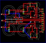
One thing for sure... this is one tight little board! If you use 1/4 watt 1% resistors they will have to be stood on end. I don't really mind this practice at all myself. Over the years I've seen MANY pieces of pro gear from Dolby and others that have been done just this way. What I did do was to alternate the positions of the bodys of them so that should they get bent over there will be less likelyhood of them touching. All in all I don't have any problems with doing it this way.
One more thing we all need to get straight here and perhaps develop is a resistor value chart for this "universal board" showing the values of the resistors used in the different Alephs. Since this test circuit is going to be a Mini-A I am goig to make R-12, 14, and 16 750 ohms. R-13 will be 47.5K, and R-17 at 392. I will leave the feedack values just the way they since we are sticking with the balanced input. I will leave out R-6 for now since my input fets are very well matched, but we can all go back and explore tunning that value once this board is up and running. I will need advice from Brian and others on this matter so those that are qualified to chime in please do so. I would like to see a chart developed to refer to for the correct values for those positions depending on what model Aleph you want to build. It will make it alot less confusing for those that are new to this project.
Thanks!
Mark
Banned
Joined 2002
Banned
Joined 2002
Banned
Joined 2002
Make your board design with provisions for PCB terminal blocks for input and output as Brian did. Why not put the bridge rectifiers on the board with enough space for large PCB heatsinks for them so external wiring would be minimal. It would also be interesting to see the schematic you are using and what values you plan on using for the Mini Aleph.
Output boards!
I would like to know how well 3W panasonic resistors will fit the ouput board. I know it's specified for 2W resistors, but I would like to use the boards with my upcoming Aleph-X and already have some 3W panasonic resistors I want to use. Also can the output board handle a Aleph-X biased around 6-8 amp? If not I will have to change me amount in the Wiki.
Thanks
Martin
jleaman said:
I hope brian puts on cut lines and that the pcb place makes it easy to snap them : O ) NOt may of us have a band saw. But a exacto Knofe worked for tbe Gain clone kit's.
The boards will have scoring, as with my Chipamp boards, which will allow them to be easily cut apart. They were not meant to be cut apart with a hacksaw, but for the prototypes, it wasn't possible to get scoring.
--
Brian
Mark A. Gulbrandsen said:I just posted a fresh batch of photos on Brian's gallery.
One thing for sure... this is one tight little board! If you use 1/4 watt 1% resistors they will have to be stood on end. I don't really mind this practice at all myself. Over the years I've seen MANY pieces of pro gear from Dolby and others that have been done just this way. What I did do was to alternate the positions of the bodys of them so that should they get bent over there will be less likelyhood of them touching. All in all I don't have any problems with doing it this way.
One more thing we all need to get straight here and perhaps develop is a resistor value chart for this "universal board" showing the values of the resistors used in the different Alephs. Since this test circuit is going to be a Mini-A I am goig to make R-12, 14, and 16 750 ohms. R-13 will be 47.5K, and R-17 at 392. I will leave the feedack values just the way they since we are sticking with the balanced input. I will leave out R-6 for now since my input fets are very well matched, but we can all go back and explore tunning that value once this board is up and running. I will need advice from Brian and others on this matter so those that are qualified to chime in please do so. I would like to see a chart developed to refer to for the correct values for those positions depending on what model Aleph you want to build. It will make it alot less confusing for those that are new to this project.
Thanks!
Mark
As for the resistors, the layout is intended for compact 0.5w metal film resistors which have a body length of 0.126", working well with the 0.2" spacing. I will post a parts list soon for the project..
Here is a picture of the metal film resistors, used in my mic preamp prototype:
http://chipamp.com/diyaudio/micpre-assembly-highres.jpg
As for the resistor values, we can work up a chart of values for the circuit. R6 isn't needed, but I included it on the layout for optimal input fet matching, as Nelson did on the A30.
--
Brian
I just posted a few more pictures in Brian's gallery. All I need are three 750 ohm ressitors to complete this channel and we can test it. Because everything in the State of Utah is closed on Sunday this will have to wait till tommrrow...... fortunately I only work a mile from Ra-Elco! Check back tommrrow night for more pictures and hopefully a working Mini-A channel.
Mark
Mark
- Status
- This old topic is closed. If you want to reopen this topic, contact a moderator using the "Report Post" button.
- Home
- Amplifiers
- Pass Labs
- New Aleph Mini PCB GB