Hi all,
The building of my zen amp goes slowly but surely. I finally found some suitable heatsinks and I could do my tests yesterday and adjust the bias for symetrical clipping.
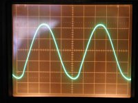
However, with a sinusoidal signal at the input, the output signal looks good until it reaches about 7 Vrms, afterwards there seems to be some distorsion in the peak of the minimum portion of the signal (as seen in the picture below).
The same thing happens for both channel. So either this behaviour is normal or there is some part of the circuit that is common to both channel that is defective.
Any clues ?
Thanks and best regards,
The building of my zen amp goes slowly but surely. I finally found some suitable heatsinks and I could do my tests yesterday and adjust the bias for symetrical clipping.
However, with a sinusoidal signal at the input, the output signal looks good until it reaches about 7 Vrms, afterwards there seems to be some distorsion in the peak of the minimum portion of the signal (as seen in the picture below).
The same thing happens for both channel. So either this behaviour is normal or there is some part of the circuit that is common to both channel that is defective.
Any clues ?
Thanks and best regards,

I'd say you're running right about to spec. The Zen is not a huge amplifier. 7Vrms is about 20Vp-p, which is a fairly realistic estimate of what to expect from a single-ended 33V rail using MOSFETs for outputs.
If you want more voltage swing (i.e. more power), you can always increase the rail, but keep an eye on the heat dissipation or you'll fry your output devices. Beyond that, you'll need to consider other options, such as parallel channels or using a different circuit topology...
Grey
If you want more voltage swing (i.e. more power), you can always increase the rail, but keep an eye on the heat dissipation or you'll fry your output devices. Beyond that, you'll need to consider other options, such as parallel channels or using a different circuit topology...
Grey
GRollins said:I'd say you're running right about to spec. The Zen is not a huge amplifier. 7Vrms is about 20Vp-p, which is a fairly realistic estimate of what to expect from a single-ended 33V rail using MOSFETs for outputs.
Grey
Well I'm a bit confused,
Judging from the original zen schematics, I use exactly the same setup. 2 x 25V transfo output etc... So 7Vrms is only about 6W in 8 ohms. Why would they specify the zen at 10W ?
The only thing that is different are the MPSA92. I used MPSW92, which according to the specs are the exact same thing.
I have made some research through the forum (pass labs) One thing I will try as soon as I can, will be to put a resistor (220 ohms) in serie with the gate of Q1 on the transistor end.
jcayer said:Hi,
thanks for taking the time to reply")
Rails = 33.4 Volts
Bias = 16.8 Volts
Sorry, I meant, bias current. What size is R1?
I guess, while I'm at it. What kind of load are you testing with, and what frequency are you testing at?
--
Danny
azira said:
Sorry, I meant, bias current. What size is R1?
I guess, while I'm at it. What kind of load are you testing with, and what frequency are you testing at?
--
Danny
Danny,
R1 is .33 2W and the IBias is 2 amps (very close)...
I'm testing with some 8 ohms power resistors (50 W)
And the picture was taken with 1KHz signal.
Ok... I'm no where near as expert on these things as some people around here but I bet you're RIGHT on the edge of some asymmetric clipping.
Firstly, to deliver 10W into 8-ohms you only need about 1.25 Amps of current and around a 20 Volt rail + some headroom. So your amp is capable of delivering that in it's present state.
But, your image shown is about 9Vrms = 12.7Vpeak would get the negative cycle down to around 4 Volts. The .pdf from passdiy doesn't mention when clipping should occur and I honestly haven't measured my own yet. But from experience, I would say that getting lower than 3 Volts DS accross a FET is getting into clipping.
I would say that you should go ahead and increase your input signal a little more so that you'll see pronounced clipping, adjust P1 to make it symmetrical and then back off the input and see if the negative "bump" is still there and assymetrical.
Sorry, it's not super helpful advice..
--
Danny
azira said:Ok... I'm no where near as expert on these things as some people around here but I bet you're RIGHT on the edge of some asymmetric clipping.
...
I would say that you should go ahead and increase your input signal a little more so that you'll see pronounced clipping, adjust P1 to make it symmetrical and then back off the input and see if the negative "bump" is still there and assymetrical.
Sorry, it's not super helpful advice..
--
Danny
Danny,
P1 is adjusted, the clipping looks like it is symetrical, The peaks just flatten simultanously. But this "strange" bump appears around 7Vrms and stays on.
I will try to change the pots (along with adding the resistors at the gate of Q1) for one turn pots. When I mounted this board, I had only some multiturns and I hate playing with these pots
Thanks for your help,
The specific Zen hasn't been identified, but keep in
mind that most of them have a low input impedance.
It is possible that the signal source is doing something
at that level.
The orginal Zen did 10 watts at 2%, which is just visible
with a scope, and yes, you can figure on swinging rail to
ground, losing less than 3 volts at each end.
mind that most of them have a low input impedance.
It is possible that the signal source is doing something
at that level.
The orginal Zen did 10 watts at 2%, which is just visible
with a scope, and yes, you can figure on swinging rail to
ground, losing less than 3 volts at each end.
Nelson Pass said:The specific Zen hasn't been identified, but keep in
mind that most of them have a low input impedance.
It is possible that the signal source is doing something
at that level.
Zen version 1
I never tought that the source could do something like that...
I tested the BOZ with the same source (function generator) and the signal was very goog. Of course the input impedance are not the same (BOZ vs Zen v.1)
I will try to feed the Zen thru the BOZ. That might do it. I really hope that you are right, because I don't know what else to try / test beside changing the parts
Nelson Pass said:Since you have a scope, you should be able to verify
all the voltages and such to confirm proper supply and
bias. Since the first Zen is so dead simple, it can't be
too hard to find the problem. If it's your source, you
should see that distortion at the input.
Nelson,
The input is ok, I borrowed another signal generator and made a test on my lunch hour.
Same bump...
However, I cranked the adjustment pot a bit more and the signal got better. Now, at 10W (8ohms - 1KHz) the signal is perfect. But when it reach clipping, it is not symetrical.
And I measured the dc drain voltage and the bias voltage is running at around +19.7V. (both channels)
Is it too high ??
Thanks for your input
Nelson Pass said:What do you mean by Drain Voltage vs bias voltage?
I'm sorry, I should have "reread" my post
I meant the drain voltage of Q1 and Q2... (19.7 Volts)
Nelson Pass said:Normally I would have expected best performance at about
17-18 volts, but going back to the original article I note that
it says "adjust for symmetric clipping", so what's a couple
volts among friends?
Thank you Mr. Pass.
Right now I am satisfied with the signal.
I think that my confusion came from the fact that I built the BOZ first and I almost didn't have any adjustment to do. The clipping was symmetrical and very sharp right from the beginning.
Now I will try to find some time in the next couple of days (damn kids
) to plug the BOZ to the zen just to monitor the outputs and then THE big test with my cd player and my speakers...Now I wonder, what tune shall be the first ??
Any suggestions ?
- Status
- This old topic is closed. If you want to reopen this topic, contact a moderator using the "Report Post" button.
- Home
- Amplifiers
- Pass Labs
- help with zen waveform