Ok, 2 questions. I've searched and searched and haven't found a great explaination about how to adjust ac current gain on an aleph 2. Most explainations tell what to set it to, not how to set it. Anyway, if someone could explain this to me, that'd be great, or at least give me a link that says how to adjust it. Some info, i'm going to be using 16 outputs per channel of irp240.
i'm using 1 ohm source resistors and for the output resistors i'm using mra-12 mills .22 ohm x3 in parallel. i'm gonna set the bias w/ a 100k pot for r19, and i may have a switch that can switch between 2 or 3 different parallel resistors eventually to have the bias set for fall/summer/winter settings (i can use a dpdt switch to adjust ac current gain as needed as well, but i need to know how to adjust ac current gain)
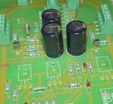
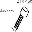
also, i'm using ztx450's, can someone look at the layout and make sure that they are the correct orientation? thanks!
-Matthew K. Olson
i'm using 1 ohm source resistors and for the output resistors i'm using mra-12 mills .22 ohm x3 in parallel. i'm gonna set the bias w/ a 100k pot for r19, and i may have a switch that can switch between 2 or 3 different parallel resistors eventually to have the bias set for fall/summer/winter settings (i can use a dpdt switch to adjust ac current gain as needed as well, but i need to know how to adjust ac current gain)
also, i'm using ztx450's, can someone look at the layout and make sure that they are the correct orientation? thanks!
-Matthew K. Olson
Attachments
Ok, very cool. THATS the link i was looking for. Lets see if i get this straight.
i measure voltages across resistors
voltage across one source resistor VRS
voltage across output resistors VRO
and in the case of aleph 2, i adjust r21 to get proper ac current gain....
so the math
VRO/ (output resistance) = x amount of current
VRS/ (source resistance) = y amount of current
[1 - (y/x)] x 100 = ac current gain percentage
an example w/ my numbers might be:
.05v / .07 ohms = .71A
.05v/ (16 fets total, and 1 ohm source resistors = .0625 ohms) = .8A
.8A/.71A = 110% ac current gain ...yikes ...hope i don't measure .05 v across all those resistors!
is this math theoretically correct though, assuming i measured .05v across those resistors...which i didn't
??
thanks guys, just trying to clarify things for the morons like me")
-Matthew K. Olson
i measure voltages across resistors
voltage across one source resistor VRS
voltage across output resistors VRO
and in the case of aleph 2, i adjust r21 to get proper ac current gain....
so the math
VRO/ (output resistance) = x amount of current
VRS/ (source resistance) = y amount of current
[1 - (y/x)] x 100 = ac current gain percentage
an example w/ my numbers might be:
.05v / .07 ohms = .71A
.05v/ (16 fets total, and 1 ohm source resistors = .0625 ohms) = .8A
.8A/.71A = 110% ac current gain ...yikes ...hope i don't measure .05 v across all those resistors!
is this math theoretically correct though, assuming i measured .05v across those resistors...which i didn't
??
thanks guys, just trying to clarify things for the morons like me
-Matthew K. Olson
Mattyo5 said:Also, do I have a signal playing , like 1khz sine when i do this?
-Matthew K. Olson
Your math seems OK but you didn't read the book carefully.
Yes 1K will do. Only, it's such an annoying tune. I prefer lower like 100Hz.
/Hugo
Ah, one other thing i thought of. Does the bias setting of r19 effect the ac current gain settings?
I'd like to have perhaps 3 settings, summer winter etc. so, what if i set the bias to a switch, 3 different settings maybe 1,2,4A bias per side, then use that switch on those settings and set the ac current gain. Or do i need to set the bias on one setting, then set the ac current gain, then set the bias, then set the current gain, then set the bias on the last setting, then set the current gain? Sorry if this doesn't make sense, just trying to get an idea of procedure here. who knows, the amp my blow up and i may never get it running haha.
-Matthew K. Olson
The maximized setting of the A2 with 3A bias is as you see it in the schematic. Those values will yield 69% ACI gain and with 10Apk of current limit (R16=100ohms) the A2 will peak at 40V and 10A.
BTW, lower percentages of the ACIG will only yield earlier distortion setting in on the +V and +I part of the signal. It will not lower overall bias current...changing the Source resistors will.
BTW, lower percentages of the ACIG will only yield earlier distortion setting in on the +V and +I part of the signal. It will not lower overall bias current...changing the Source resistors will.
Well, i added 4xtra fets per channel, effectively throwing off the stock value of r21. So, i'm sure i'll have to play with it a bit. I know 50% is ideal efficiency, and stock is 69%, so i will play with it in there. Perhaps when i chance to low bias setting i'll set ACIG to 50%, and when i use high bias i'll set it at 65-70%. Gotta love those DPDT switches
-Matthew K. Olson
-Matthew K. Olson
two things,
1. most multimeters don´t measure right above 400Hz so if it´s not a true RMS meter choose a lower value.
2. The bias setting does have influence on the ac-current-gain. When you set the bias higher, ac-current-gain will go down.
The amount of current added by the active current source will stay the same but since the bias is higher the percentage will go down.
William
Also, as you adjust the bias the power supply voltage will change and that may make a difference too.
Here is what I did:
I used two potentiometers as temporary substitutes for the resistors that set the bias and the AC current gain. Then I set a bias point, ran the equations to determine what voltage drop to look for across the source resistors at my desired AC current gain, and then adjusted the AC current gain via the pot. Now I removed the pots and measured their values. I repeated the above for other bias points. Just plug the amp into a regular wall socket during the adjustments
The problem was that the amp sounded best at the higher bias point so I just left it at that, but at least my curiosity was satisfied.
Bill
- Status
- This old topic is closed. If you want to reopen this topic, contact a moderator using the "Report Post" button.
- Home
- Amplifiers
- Pass Labs
- more aleph 2 questions