Hi guys,
This is my first DIY audio project that doesn't have wood and drivers in it. I am constructing a Pass A30 and am starting to see things come together. I am not near power up but a lot of the construction has been completed.
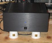
The chassis is (what I think is) unique. The cross section is a "H" with the PSU entirely below and the amp above. The uprights of the "H" are entirely heatsink. The "-" of the "H" is a 1/2" thick aluminum plate with some welding steel and a piece if 2oz double sided fr4 anong with another 3/32 alu plate laminated together. This will serve to shield the 2 compartments from each other. The front plate will also be 75% heat sink for the bridges. The outputs are secures to the "-" with alu bar. The "-" appears to be "hardcoated and will only see heat sink compound with no mica etc.
All aspects are surplus/bargain items. The amp boards are home brew based on a layout by "Asen". The boards you see are for experimentation and the real boards will have higher qual components etc. The Transformers are 250VA 21+21 secondaries. There are 5x15,000uf caps per rail....4 rails as it is dual mono (for 300,000uf total) They are 35v 105C snap in caps. Experimentation tells me I will see approx 26v rails under load. I am integrating a soft start - powering through a resistor - and a relay to short the resistor after all charges.
I have seen a signature by a forum member reading: "All right, who's next to be ridiculed" ...Is it me?
Seriously, constructive criticism is welcome..especially from you guys!
 Sorry if some pics are big
Top View:
Another top:
"H" cross section:
Up side down PSU view:
This is my first DIY audio project that doesn't have wood and drivers in it. I am constructing a Pass A30 and am starting to see things come together. I am not near power up but a lot of the construction has been completed.
The chassis is (what I think is) unique. The cross section is a "H" with the PSU entirely below and the amp above. The uprights of the "H" are entirely heatsink. The "-" of the "H" is a 1/2" thick aluminum plate with some welding steel and a piece if 2oz double sided fr4 anong with another 3/32 alu plate laminated together. This will serve to shield the 2 compartments from each other. The front plate will also be 75% heat sink for the bridges. The outputs are secures to the "-" with alu bar. The "-" appears to be "hardcoated and will only see heat sink compound with no mica etc.
All aspects are surplus/bargain items. The amp boards are home brew based on a layout by "Asen". The boards you see are for experimentation and the real boards will have higher qual components etc. The Transformers are 250VA 21+21 secondaries. There are 5x15,000uf caps per rail....4 rails as it is dual mono (for 300,000uf total) They are 35v 105C snap in caps. Experimentation tells me I will see approx 26v rails under load. I am integrating a soft start - powering through a resistor - and a relay to short the resistor after all charges.
I have seen a signature by a forum member reading: "All right, who's next to be ridiculed" ...Is it me?
Seriously, constructive criticism is welcome..especially from you guys!
Sorry if some pics are big Top View:
An externally hosted image should be here but it was not working when we last tested it.
Another top:
An externally hosted image should be here but it was not working when we last tested it.
"H" cross section:
An externally hosted image should be here but it was not working when we last tested it.
Up side down PSU view:
An externally hosted image should be here but it was not working when we last tested it.
Banned
Joined 2002
mpmarino said:Goucho,
There is a piece of sheet steel in the lamination. Welding Iron..
Marc
Perfect!
Interesting idea, kinda like the front heatsink with "chopped" top ...
Btw - only one remark though ... My first version of Zen was a little bit similar - I mean - PSU "in the basement" and circuitry on the top and all ...
What I discovered during mods:
- to change/experiment with anything I had to dissassembled whole amp
- there was hum (OK, you have much better shielding than I did and I had my transistors conected to PCB through some wires)
- so in my mkIV version - I've put PCB directly to heatsinks (verticaly) and I've moved trannie as much away as possible ... Hum disapered and also mods are much much eayier now
Stabist,
Yes, I'm sure your right about the potential for hum. I have every intention of possibly mounting the toroids vertically (or whatever) if that is the case.
The bottom panel will be just as easy to remove as the top, so the toughest part of servicing the PSU will be to flip the whole thing over....the sucker's gonna be heavy!
Marc
Hi!
Yes stupid me - it's quite obvious it was around 2am here in SLO when I saw my upper reply ... It's very clearly seen how the PSU is mounted ...
Way beter than mine version ...
Btw - considering you have transistor mounted directly to PCB and that the shield between PSU and PCB is quite massive - I think that won't cause hum. BUT! be very carefull how to route input and output wires ...
Yes stupid me
- it's quite obvious it was around 2am here in SLO when I saw my upper reply ... It's very clearly seen how the PSU is mounted ... Way beter than mine version ...
Btw - considering you have transistor mounted directly to PCB and that the shield between PSU and PCB is quite massive - I think that won't cause hum. BUT! be very carefull how to route input and output wires ...
Thanks for your posts Stabist,
Not only is getting the thing to work at all a concern for me,...but unnecessary noise is as well. Your advice is appreciated.
Marc
No..not at all, all you say is valid in my opinion
Not only is getting the thing to work at all a concern for me,...but unnecessary noise is as well. Your advice is appreciated.
Marc
Yes stupid me
No..not at all, all you say is valid in my opinion
Hi!
Btw - another remark - is it good taken care for air convection flow - or does this middle section represents a barrier ... One thing I learned was also - allow enough natural air flow capacity to the amp - and you'll be amazed how much you can gain in cooling it down ... I mean - my Zen vas at first on "small" legs - about 2cm from surface - after adding additional suport under those legs - so I got around 10cm distance to the floor - tha temp droped for few degres!
Btw - another remark - is it good taken care for air convection flow - or does this middle section represents a barrier ... One thing I learned was also - allow enough natural air flow capacity to the amp - and you'll be amazed how much you can gain in cooling it down ... I mean - my Zen vas at first on "small" legs - about 2cm from surface - after adding additional suport under those legs - so I got around 10cm distance to the floor - tha temp droped for few degres!
"Btw - another remark - is it good taken care for air convection flow - or does this middle section represents a barrier ... One thing I learned was also - allow enough natural air flow capacity to the amp - and you'll be amazed how much you can gain in cooling it down ... I mean - my Zen vas at first on "small" legs - about 2cm from surface - after adding additional suport under those legs - so I got around 10cm distance to the floor - tha temp droped for few degres!"
Good point Stabist. I now intend to use heavy duty screen for the top and bottom panel. The screen is steel and is about 60% air with 1/8" holes normally used for RF eqpt. Also, I will perf the rear panel liberally in the psu section. I will raise the amp on feet about 2.54 cm (yup, I can do metric too ) Do you think this will be sufficient?
Marc
Good point Stabist. I now intend to use heavy duty screen for the top and bottom panel. The screen is steel and is about 60% air with 1/8" holes normally used for RF eqpt. Also, I will perf the rear panel liberally in the psu section. I will raise the amp on feet about 2.54 cm (yup, I can do metric too
) Do you think this will be sufficient?Marc
Nice looking amp..real nice. I found some nice adjustable height feet today..they would normally live under a Nokia telecom switch ! They should give me 1-2" adjustability.
I fired up my PSU last night. I have a little work to do to get the soft start working perfectly but I am very positive ...it works 'OK' now.
I was amazed..I had a bulb in series with the mains and it actually went out after the caps charged!! I really expected a dead short somewhere but it was fine the first time around..cool. Things are real tight in there and the chance of error was high..especially for a first timer. I havent checked the ripple on the scope yet but my fingers are crossed.
Hey..in a couple of years I might have a working amp. In the meantime, the X boards I am expecting from Kari will be calling me in my sleep
YEE HA! after much troubleshooting I have music.
The gain is surprisingly low but I was expecting that. I abandoned the boards I was using.
I powered the boards I had a few weeks ago and it didn't come up. I did a little poking around in there only to realise that I haven't learned much at all about what I am building here. Goobye boards, hello P2P.
I find that I am probably more familiar with this circuit than I would have been otherwise.. (going P2P).
A couple of questions..
I notice that my rails have sagged more than I expected. I estimated +-~25v and ended up with +-21v. think the reason is as follows: ((FYI: I am completely stock on the amp circuit EXCEPT I am using IRFP450 and mpsa18.. I have a ton of them.) Across the .47R source resistors I am seeing ~.87v. almost 2A per device..3 ccs and 3 op per side = almost 6A bias Holy SH! My sinks are still touchable after 40 min or so.
Hey, should I leave it like that or am I pushing it a bit?? I could lower R19 or is it the mpsa18 maybe? Is my assumption that lowering the bias some will bring my rails up a bit reasonable?
It's pretty ugly now so pics are a ways away
The gain is surprisingly low but I was expecting that. I abandoned the boards I was using.
I powered the boards I had a few weeks ago and it didn't come up. I did a little poking around in there only to realise that I haven't learned much at all about what I am building here. Goobye boards, hello P2P.
I find that I am probably more familiar with this circuit than I would have been otherwise.. (going P2P).
A couple of questions..
I notice that my rails have sagged more than I expected. I estimated +-~25v and ended up with +-21v. think the reason is as follows: ((FYI: I am completely stock on the amp circuit EXCEPT I am using IRFP450 and mpsa18.. I have a ton of them.) Across the .47R source resistors I am seeing ~.87v. almost 2A per device..3 ccs and 3 op per side = almost 6A bias
Holy SH! My sinks are still touchable after 40 min or so. Hey, should I leave it like that or am I pushing it a bit?? I could lower R19 or is it the mpsa18 maybe? Is my assumption that lowering the bias some will bring my rails up a bit reasonable?
It's pretty ugly now so pics are a ways away
- Status
- This old topic is closed. If you want to reopen this topic, contact a moderator using the "Report Post" button.
- Home
- Amplifiers
- Pass Labs
- A30....I still have a ways to go !!!