Hi all,
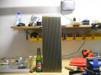
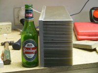
I have 2 of these heatsinks which are 430mm long X 170mm High and fin length is 95mm on a 12 mm slab of aluminium. There are 33 fins in total.
Sorry didnt have the standard measure coke can, but I think beer bottle is universal size too
Question is how do I estimate the C/W on these things?
I am building aleph-x and want both channels in one enclosure.
Tx is 18 0 18 rails 24 volts bias 8 amp
Total power per channel is 384
In thinking one aint gonna quite cut it for near 800 watts?
Your opinions appreciated.
Attachments

This might be useful
Rod Elliott has made a spreadsheet to estimate thermal resistance which may be useful: http://sound.westhost.com/heatsink.zip
I put some quick figures in... William's estimate is probably about right
Rod Elliott has made a spreadsheet to estimate thermal resistance which may be useful: http://sound.westhost.com/heatsink.zip
I put some quick figures in... William's estimate is probably about right
Gee, that was fast
3 replies in ten minutes... lol
I had a closer look at the photos, and you say the heatsink is 170mm wide with 33 fins, that means that the space between them is around 5mm. Since air moves slower when in closer contact with the surface (laminar flow), a fan is probably a good idea. Also, the shiny surface ain't the best for radiation...
So maybe the earlier estimates were perhaps a little optimistic
Thumb rule calculation C/W= 50 /( Sqr A ) ,- A in sqr cm's suggests somewhere in the vicinity of 0.25....
These will have to used vertically to be most effective, and very long fins loose efficiency somewhat............
Better test it with a power resistor and controlled current, and measure the temp. rise...?? I use some 50 W metal case resitors for heat sink mount.
One solution could be to cut them in two halves mounted sideways, giving a combined 21 cm high 34 cm deep block...??
Do some calcs before you decide...
Here is a link to some heat sink theory and a calculator spreadsheet.
Th calculator valuis far to optimistic, I think.. possibly because of the very long fins
http://sound.westhost.com/heatsinks.htm
And another
http://w1.859.telia.com/~u85920178/begin/heat-0.htm
Thanks all for your help.
I have never seen one of these calculators, but Rods one tells me that its 0.0896 C/W. Ive jigged my bias etc to get about 6.8 per channel as I have just bought some .22 0hm resistors from Steve at apex and thought I should use them
Any way Im now looking at 650 watts so i get 59 degrees above ambient. This isnt going to work so its long like Im going to have to build monoblocks again. More metalwork and two transformers I have to ship from Aussie.
Thanks all for your help.
BTW any one remember Nelsons rule of thumb on heatsink temp. Was something about if you can touch the sink for a few seconds only its around ......

Just had another look and its actually 500mm long. Ive just been playing with this calculator and Im not sure if its correct. The change between 250mm to 500mm is 0.0936 to 0.0881? Can this be right or does the calculator assume a point source for the heat and not distributed?
It may make sense to cut one in half and build two monoblocks.
cheers Arthur
It may make sense to cut one in half and build two monoblocks.
cheers Arthur
~0.09K/W... that is probably too optimistic.
What numbers did you enter into the spreadsheet? Also, you will probably have to alter the emissivity entered into the spreadsheet because the material the heatsink is composed of will deviate from "blackbody" radiation.
In any case, I doubt the accuracy of Rod's spreadsheet in this instance because of the relatively small spacings between fins and associated restricted airflow. A fan would probably help these heatsinks a great deal.
The calculator makes some assumptions in respect to air flow, radiation coefficients etc.
Your fins are very close, which reduces air flow, - IOW efficiency. It is also very long.
If you look at heat sink specs in general, - a doubling of length does not halve the thermal resistance, - it follows a somewhat exponentional curve. That's why I said you'd be better off cutting the long pieces in two halves and mount sideways.
You could do some surfing, to see if you find a fairly similar profile...that could give a clue...
I have a set of 4, ( A-X ??) of 20 cm wide 30 cm high, 8 cm fin depth and 17 fins. These came out appx. 0.23 in actual measurement, dissipating 100 w from 2 resistors.
See if you can get hold of a couple of resitors for heat sink mount, and do a test.
A snip from Rod's site
SNIP:
The average performance of a typical heat sink is linearly proportional to the width of a heat sink in the direction perpendicular to the airflow, and approximately proportional to the square root of the fin length in the direction parallel to the flow. For example, an increase in the width of a heat sink by a factor of two would increase the heat dissipation capability by a factor of two, whereas doubling the depth or height will only increase the heat dissipation capability by a factor of 1.4. Therefore, if the choice is available, it is beneficial to increase the width of a heat sink rather than the length of the heat sink fins. Also, the effect of radiation heat transfer is very important in natural convection, as it can be responsible of up to 25% of the total heat dissipation. Unless the heatsink is facing a hotter surface nearby, it is imperative to have the heat sink surfaces painted or anodised to enhance radiation.
Even better: read the whole article, sect. 17 in particular
Luke said:Hi Audiousername,
your probably right about fin spacing and accuracy, but not sure why you doubt its 0.08, its half a meter long and fins are 115mm long and theres 33 of them. It hurts to lift this beast
I don't doubt that it hurts to lift them
Quite the beastly heatsinks...Were they salvaged from old equipment? If so, perhaps where they came from may give an idea of the thermal resistance
Hi AuroraB,
Ive just realised my emissivity was out so I set it to 0.7 for annodised alumimium. It now reads 0.0407. this thing could could sink the pass monster being designed
To be honest its getting late and my brains getting slow. Will have another look again tomorrow. Thanks for your help.
audiousername,
they are salvaged, I think from a mainframe power supply. I never saw it with any silicon attached or what it came out of.
I want to annodise it black (currently gold) and make it the front panel with blue leds in there
Another thing I though of, is build it and then see how hot gets, then make the cases. Not really an engineering approach but should work
You can also mount a couple of resistors on it, get some current flowing and measure power and temperature. I did this to get a performance rating of my heatsinks.
see http://www.diyaudio.com/forums/showthread.php?s=&threadid=20493 for more info.
see http://www.diyaudio.com/forums/showthread.php?s=&threadid=20493 for more info.
- Status
- This old topic is closed. If you want to reopen this topic, contact a moderator using the "Report Post" button.
- Home
- Amplifiers
- Pass Labs
- any idea what these will dissipate?