Yes, I know this topic has been beaten to death, but I wasn't able to find an answer to this question....
Yes, H.H - I did search...")
Take just about any standard flatback heatsink. Now imagine taking 3 of them and laying them next to each other like this:
E
E
E
If I take a piece of 1/4" aluminum flat plate and cut it to the correct dimension and then bolt the heatsinks to it (using grease), does this raise or lower the thermal efficiency? I'm wondering if I can buy smaller extrusion and ultimately achieve the same thermal efficiency as using a larger one...
This is what I'm envisioning (the vertical lines would actually be one continuous piece of metal):
|E
|E
|E
I ask this question because I've seen many TO3 style amps that have been designed using a "carrier" to mount the TO3's which is then bolted to the heatsinks... It seems to me that this would significantly raise the junction temps but it doesn't seem to be a problem... The carriers often look like this (only the heatsink is actually one large extrusion):
.E
[E
.E
How would one go about calculating the thermal sinking of the combination of the two pieces of metal? Just add their dissipations together and subtract the joint loss? Or, is it not so simple?
Any help would be appreciated!
Thanks,
Yes, H.H - I did search...
Take just about any standard flatback heatsink. Now imagine taking 3 of them and laying them next to each other like this:
E
E
E
If I take a piece of 1/4" aluminum flat plate and cut it to the correct dimension and then bolt the heatsinks to it (using grease), does this raise or lower the thermal efficiency? I'm wondering if I can buy smaller extrusion and ultimately achieve the same thermal efficiency as using a larger one...
This is what I'm envisioning (the vertical lines would actually be one continuous piece of metal):
|E
|E
|E
I ask this question because I've seen many TO3 style amps that have been designed using a "carrier" to mount the TO3's which is then bolted to the heatsinks... It seems to me that this would significantly raise the junction temps but it doesn't seem to be a problem... The carriers often look like this (only the heatsink is actually one large extrusion):
.E
[E
.E
How would one go about calculating the thermal sinking of the combination of the two pieces of metal? Just add their dissipations together and subtract the joint loss? Or, is it not so simple?
Any help would be appreciated!
Thanks,
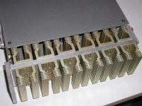
I once tried to make a large heat sink out of many small ones. It was for Zen amp. But since there were only 2 transistors attached to the sink the heat distribution wasn't even and some spots were much warmer than the others even after many hours of operation (I used thermal grase).
I liked the looks anyway.
I plan to build Aleph 5 on that and with 6 transistors per side it should work really fine. I usually don't do calculations as well. It either runs hot or not at all.
I liked the looks anyway.
I plan to build Aleph 5 on that and with 6 transistors per side it should work really fine. I usually don't do calculations as well. It either runs hot or not at all.
Attachments
Heatsink Calculation
Last time I tried to calculate a heatsink, I put my amp at 100ºC...''
I guess you can allways try to bolt a single power resistor (with aluminium housing), apply a voltage until the heatsink get the temperature you want (say 50ºC), then read the tension and P=R^2/R. You get the maximum power dissipation of the heatsink before you drill all the dissipators to put the transistors and / or resistors.
Pedro Oliveira
PS: I agree with Nelson Pass: Bigger is better at least in heatsinks.
Last time I tried to calculate a heatsink, I put my amp at 100ºC...'
'I guess you can allways try to bolt a single power resistor (with aluminium housing), apply a voltage until the heatsink get the temperature you want (say 50ºC), then read the tension and P=R^2/R. You get the maximum power dissipation of the heatsink before you drill all the dissipators to put the transistors and / or resistors.
Pedro Oliveira
PS: I agree with Nelson Pass: Bigger is better at least in heatsinks.
Bigger is better with heat sinks and bias current
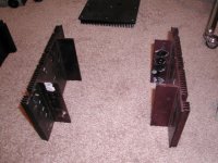
If you want to use multiple heatsinks, you are best to mount the transistors on each individual heatsink and then use strap or angle pieces to mechanically join each heat sink around the edges. Just keep the number of devices per heatsink equal.
If you want to use multiple heatsinks, you are best to mount the transistors on each individual heatsink and then use strap or angle pieces to mechanically join each heat sink around the edges. Just keep the number of devices per heatsink equal.
nice link, herm
I checked out some of the sheet goods and related prices. They compete well with prices at my local metal yard. A 3'x4'x1/16" piece of aluminum cost roughly $2.55/pound. New aluminum is $3.00/pound here in Portland, Oregon. Excellent lead! It's still way cheaper to buy in bulk and make your own cuts, though. They don't give their labor away.
John Inlow
Nelson Pass said:Calculations? We don't need no stinkin calculations! We just
make them really big!
Harley Davidsons are designed using a similar philosophy I think.
If you have the choice between a tall skinny heatsink and a short broad one with a same area, the short broad one will win every time. Only the first couple of inches seems to do anything much, after that the rising air has been warmed enough as it rises through the fins that it cannot cool any further fins higher up.
I love fans! I did a little test with a h/s 110mm x 95 with 11 fins 25 mm deep and 1.5mm thick, both on it's lonesome and with a 12v fan covering most of its finned side and a 25w metal clad resistor attached to the flat side with thermal paste. Here are the figures:
Heatsink vertical both sides exposed
24.25 watts
44.40 deg C rise
1.83 deg C per w
Heatsink vertical with 2.8 watt Sunon fan @ 5v
24.25 watts
10.20 deg C rise
0.42 deg C per w 4.36 times improvement
Heatsink vertical with 2.8 watt Sunon fan @ 12v
24.25 watts
7.70 deg C rise
0.32 deg C per w 5.77 times improvement
Heatsink vertical with 2.8 watt Sunon fan @ 15v
24.25 watts
7.50 deg C rise
0.31 deg C per w
Heatsink vertical with 2.8 watt Sunon fan @ 20v (12v fan, mind you!)
24.25 watts
7.50 deg C rise
0.31 deg C per w
At 5v the fan is inaudible.
GP.
heatsink question
Yes, mostly bigger is better. But how much bigger do you need to be better? So, even if you don't wont any stinkin calculation, you need at least some intelligent reasonning to get to the ballpark, right?
Treat heatsinks as resistors for heat current, and dissipation as heat voltage.
Example: Your output stage dissipates 100 watts, and you want to limit the max temp to 90 degrees at 40 degrees ambient, this is a temp rise of 50 degrees, right? You need a heatsing that has at most 0.5 degrees per watt "resistance". Using a larger heatsink of say 0.25 degrees per watt resistance, multiply by the dissipation gives 0.25 times 100 is 25 degrees temp rise above ambient.
If you use a bracket between the output transistors and the heatsing, that add "heat resistance" in series to the heatsink.
There is also the "heat resistance" of transistor junction to case, say 0.15 degrees per watt (don't know how realistic this is, look at the data sheet).
Example: use the 0.25 degrees per watt heatsink with a bracket that adds say 0.1 degrees per watt, and a transistor with a 0.15 degrees per watt juntion to case heat resistance, total 0.5 plus 0.1 plus 0.15 = 0.5 degrees per watt. With your 100 watt dissipation that gives 100 times 0.5 equals 50 degrees temp rise. With 40 degrees ambient that gives a max temp of the output transistor junction of 90 degrees.
Easy. It's surprising how far you can yet in amplifier design with just some secondary school math....
Cheers, Jan Didden
Hi Circlotron,
to reduce this effect you must mount the transistors as high as possible so the temperature difference between air and sink keeps as high as possible. In most amps I see people mount the transistors as low as possible for some mysterious reason.
love fans too! I can get away with 4x0.65°K/W for an Aleph5 (250 watts dissipation) and a bit over 50°C heatsink temp.
Apogee,
it´s not so difficult to calculate for paralleled heatsinks. If you use 4 x 0.65°K/W you get 0.16..°K/W. You must just add the thermal resistance for the connection from aluminium to heatsink wich is quite low (measured almost <1°C difference between them)
william
Circlotron said:
If you have the choice between a tall skinny heatsink and a short broad one with a same area, the short broad one will win every time. Only the first couple of inches seems to do anything much, after that the rising air has been warmed enough as it rises through the fins that it cannot cool any further fins higher up.
GP.
to reduce this effect you must mount the transistors as high as possible so the temperature difference between air and sink keeps as high as possible. In most amps I see people mount the transistors as low as possible for some mysterious reason.
love fans too! I can get away with 4x0.65°K/W for an Aleph5 (250 watts dissipation) and a bit over 50°C heatsink temp.
Apogee,
it´s not so difficult to calculate for paralleled heatsinks. If you use 4 x 0.65°K/W you get 0.16..°K/W. You must just add the thermal resistance for the connection from aluminium to heatsink wich is quite low (measured almost <1°C difference between them)
william
Banned
Joined 2002
JasonL:
Go here:
http://www.diyaudio.com/forums/showthread.php?s=&postid=22723&highlight=metals#post22723
Good luck!
Go here:
http://www.diyaudio.com/forums/showthread.php?s=&postid=22723&highlight=metals#post22723
Good luck!
Nelson Pass said:Calculations? We don't need no stinkin calculations! We just
make them really big!
I love this philosophy too...
Banned
Joined 2002
Banned
Joined 2002
- Status
- This old topic is closed. If you want to reopen this topic, contact a moderator using the "Report Post" button.
- Home
- Amplifiers
- Pass Labs
- Heatsink question