blank527 said:This is a little off topic but can anyone tell me what the heat dissipation of an aleph 60 is?
On page 4 in the manual it says 240Watts.
Later in the manual it says 200Watts.
On the specs page it says 220Watts of power consumption
I wrote all that. MuuuuHahahahaha....

Nelson's Evil Laugh (TM)
Maybe someone from the forum lucky enough to be going to
the CES can make a recording of Nelson laughing
his evil laugh.")
Dennis
Nelson Pass said:
I wrote all that. MuuuuHahahahaha....
Maybe someone from the forum lucky enough to be going to
the CES can make a recording of Nelson laughing
his evil laugh.
Dennis
Aleph30 Distorsion
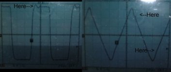
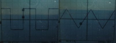
I Have distorsion quite easy to see on my Aleph30. Waveforms are ok at 1Khz, but a bump in the waveform can be see at soon as 10Khz, it is worse at 1Khz. Here the waveform, in 8ohms, at 10khz.
Any idea what can cause this distorsion and how can I remove it. One possible source, the AC gain feedback capacitor 220uf. I'm using a Panasonic FC type. Will it be better a Black Gate? What BG type?
Any suggestions?
Thanks.
Attachments
Hi Algar_emi
I also noticed similiar distortion when I tested my A30, but discovered that it was my Scope's probe leads that caused it. I don't think that the type of capacitor you use will change this problem, although higher quality caps will sound better in certain cases. BTW, can you hear this distortion, how big is this signal, is it on both channels? Did you check for possible bad solder joints? I used standard type Nichikon and Rubycon caps on my A30 and standard type Elna caps for the PSU and they all sound very good singing together.
Hope you get the cause of your'e problem and can fix it.
Aleph30 Distorsion
The sound is very detailled, with a lot of air, but lean bass.
But all this only at low level. If I tried to crank to volume, the sound change and become congested.
I have a pair of acclamed Axiom 3Ti.
My preamp is a Bride of Zen.
The distorsion I mentionned is a higher listening volume, that why I think it explained th change in sound.
As described by others users, the aleph used the active Current source to increase efficiency. So, I think that the change in sound occurs when the active current source pull the amp in class A-B mode rather that pure Class-A. The Capacitor in the current feedback path is the on passing the AC and contributing, maybe, to the distorsion. By the way, both my channels are behaving the same.
Is a better FET matching in the Current Source could eliminate this distorsion?
I will tried to open the AC feedback an listen to it...
I'm waiting for any suggestions.
When you deviate from the 50% figure for current gain
on the current source, you get more distortion at the
highest output, either because you are current-starved,
or because the current source is shutting off on negative
peaks. The cure in both cases is more bias.
Come to think of it, more bias is almost always the cure
for any limitations of Alephs.
on the current source, you get more distortion at the
highest output, either because you are current-starved,
or because the current source is shutting off on negative
peaks. The cure in both cases is more bias.
Come to think of it, more bias is almost always the cure
for any limitations of Alephs.
Nelson Pass said:When you deviate from the 50% figure for current gain
on the current source, you get more distortion at the
highest output, either because you are current-starved,
or because the current source is shutting off on negative
peaks. The cure in both cases is more bias.
Come to think of it, more bias is almost always the cure
for any limitations of Alephs.
Well we all have our Biases, some more than others.
Aleph30 Distorsion
Thanks Mr. Pass for participating to the discussion.
My current biais is 0.5A, as per Aleph30 service manual.
I adjusted the AC gain to 50% one week ago using the procedure described in one of the thread. I changed R21 from 820 ohms to 1K and got a perfect 50% gain.
My supply is using a 18+18V, 500VA transformer and the same bank of cap as the original Aleph30.
I tried using 0.8A biais but my output DC offset increased from the actual 120mv to more than 300mv! So I put it back to 0.5A.
This DC offset is causing me also a lot of problem. My input FETS are well matched. The Current and Active FET are almost identical also, except for one of the Current Source One.
Can I try to balance my Current FET by tuning one of the 221 ohms gate resistor on the FET that is different?
Mr. Pass you mentionned that R8 can be used to adjust the offset. What are the typical values to use? Do I need to used both R8 at the same time, or they are indicated at two different places?
Thanks for any comments.
Algar,
the 0,5A bias you mention, is this per fet or in total? The Aleph 30 has ca. 1.5-2A total bias and a 25 volt supply
Normally only the input diff pair is responsible for dc offset. If this changes so dramatically when changing bias I think something else is wrong.
william
the 0,5A bias you mention, is this per fet or in total? The Aleph 30 has ca. 1.5-2A total bias and a 25 volt supply
Normally only the input diff pair is responsible for dc offset. If this changes so dramatically when changing bias I think something else is wrong.
william
Aleph30 Distorsion and Traces routing
The Biais is 0.5A each, total 1.5A per rail, 3A total.
What else can be wrong? Do you have any test that I can do to start finding the problem with the DC offset?
Both my channels have the same behavior. So I exclude bad soldering and bad parts. Possible causes then are:
bad schematic to start with, but the amp is working so...
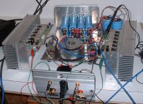
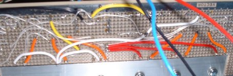
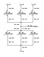
Bad traces routing. The more I think, my problem is maybe cause by the way I connected the FET using point to point wire. They are connected like this (See picture):
+V +V +V
| | |red wire (all AWG18 wires)
Q6 Q7 Q8 FET Current Source (ref Aleph30 Schematic)
|___|____|0.47 ohms and org wire
|
| wht wire
|______________________
6 resistors 0.47 ohms |
| yel wire | wht wire
Speaker out + |
|-------|---------| org wire
Q9 Q10 Q11 Active FETs
| | | org wire and 0.47 ohms
--------------------
| yel wire
-V
I suspect That the single wht wire connecting both FET banks and the single wire connectiing the Active FETs to the negative rail are choking the current and cause current limitation in the circuit.
Any suggestion for the power traces and the speaker connection point
The Biais is 0.5A each, total 1.5A per rail, 3A total.
What else can be wrong? Do you have any test that I can do to start finding the problem with the DC offset?
Both my channels have the same behavior. So I exclude bad soldering and bad parts. Possible causes then are:
bad schematic to start with, but the amp is working so...
Bad traces routing. The more I think, my problem is maybe cause by the way I connected the FET using point to point wire. They are connected like this (See picture):
+V +V +V
| | |red wire (all AWG18 wires)
Q6 Q7 Q8 FET Current Source (ref Aleph30 Schematic)
|___|____|0.47 ohms and org wire
|
| wht wire
|______________________
6 resistors 0.47 ohms |
| yel wire | wht wire
Speaker out + |
|-------|---------| org wire
Q9 Q10 Q11 Active FETs
| | | org wire and 0.47 ohms
--------------------
| yel wire
-V
I suspect That the single wht wire connecting both FET banks and the single wire connectiing the Active FETs to the negative rail are choking the current and cause current limitation in the circuit.
Any suggestion for the power traces and the speaker connection point
Attachments
I don't think the negative supply leads are the problem
assuming the front end is also sharing exactly the same
negative supply, which is necessary.
As to offset, I assume you are using a cap in the feedback
loop. As your rail voltages are a bit low, I suggest that you
reduce the 4.75K resistor feeding the NPN positive bias
circuit to 3.3 K or so to compensate. This may in fact
cure your high power distortion.
Also you can adjust the Source resistance on the current
source which feeds the input diff pair to adjust the offset.
Aleph Measurements
Thanks Mr. Pass. Your help is very appreciated.
I will tried these tonight.
You don't think my wiring can affect the sound?
I will rewire one of the channel so each current source feed one Active Fet using its own wire.
Just to be sure the rest of my circuit is Ok. Here the complete measurements:
Aleph30 Test Results
Supply Rails: +/-23.5V
Left Channel Right Channel
Diff Pair FETs Diff Pair FETs
3.751 3.745V 3.644 3.636V
offset 71mv offset 132mv
Current FETs Currents FETs
FET Vres Vgs FET Vres Vgs
Q6 .254 3.832 Q6 .245 3.735
Q7 .254 3.834 Q7 .248 3.727
Q8 .231 3.856 Q8 .241 3.729
Active FETs Active FETs
FET Vres Vgs FET Vres Vgs
Q9 .238 3.860 Q9 .220 3.947
Q10 .251 3.847 Q10 .246 3.920
Q11 .259 3.840 Q10 .242 3.923
Vres is the voltage accros the 0.47ohms on each FET.
Are the FET correctly MATCHED?
Thanks in advance.
- Status
- This old topic is closed. If you want to reopen this topic, contact a moderator using the "Report Post" button.
- Home
- Amplifiers
- Pass Labs
- Aleph 30