Here is the beginnings of my version of the High Low Pass crossover.
This is a two way design based on the earlier work of Grey and Moamps.
My plan is to build up the unit as a two way for my JBL monitors and use this as the learning curve for a more complex 4 way crossover for design and evaluation of drivers and systems at a latter stage.
Okay, its going to be completely adjustable, slope, crossover frequencies are fully variable and can be overlaped, and variable Filter Q so the exact crossover function can be dialed in for my existing speaker system. I decided to use the discrete class A opamps (by MOAMPS) rather than IC's and has provision for active unbalanced/balanced inputs and outputs.
At this stage acquired nearly all the parts and just got delivery of the Dale 1/4 watt resistors from Allied Electronics.
After a bit of trial and error etching the filter and opamp PCB's I realised the beauty of having the whole circuit on one large PCB. The layout was created the old way by cutting and pasting the printed art work onto clear laser transparency and gluing carefully in place. I used the Kinsten postive resist PCB material.
The board is about A4 size and had to be exposed in two sections for 10 minutes with a 40 watt Flouro tube. I then used roller tray to develop and etch the PCB as my usual trays just were'nt big enough.
Thanks to Moamps, Nelson and Karen for their support.
macka
Attachments
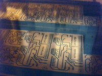
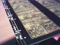
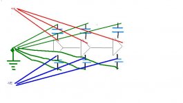
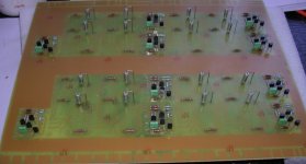
Here a wider angle of the PCB.
The white dots are where I manually marked the positions of the output coupling capacitors.
When I laid up the transparency film, the shortest signal path meant the buffers to located immediately after the filter stages. Its unremarkable that the layout in some respects will be similar to the Passlabs crossover
macka
Attachments
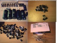
Here, some of the parts.
The capacitors are Panasonic Audio, Silmic and Panasonic FC from wkchenghk2000. His service was excellent.
The resisters are Dale R55 from Allied Electronics for all signal path elements, the other precision values will be Phillips
I am still undecided about the DC blocking capacitors. Due to shortage of PCB space I may use BlackGate N Series in E configuration. I have some large 0.01 uf polystyrene caps for the filters.
I am also unsure what to use for the 10K level. I may even use some Electro switches for that.
Any thoughts or ideas most welcome.
macka
Attachments
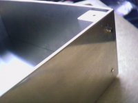
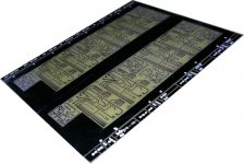
Here the case.
The 19 inch case is fabricated from 3mm sheet aluminium.
The sides, front/ back, top and bottom are held together by (4) 1 inch square solid bar sections that were turned down in the lathe as a precison matched set. Stainless steel M4 Allen key bolts are used exclusively.
macka
The 19 inch case is fabricated from 3mm sheet aluminium.
The sides, front/ back, top and bottom are held together by (4) 1 inch square solid bar sections that were turned down in the lathe as a precison matched set. Stainless steel M4 Allen key bolts are used exclusively.
macka
Attachments
The power supply is based on a zenor referenced regulator with Fet pass elements similar the the Bosoz and Ono regulator.
It will be located in a seperate mini case.
I figured that with the relatively low but steady current draw of the class A opamps the modest output impedance of the regulator should not be too much of an issue.
The ripple from the pre CRCRC filter is only 181 u at 180 milliamps using the Duncan simulator.
The board has large earth track encircling the active stages. I actually did this to save on etching copper and figured later it would help with signal earthing both channels.
I plan to run seperate dirty supply earths wires to each filter and opamp back to a star ground point along with individual +- supply wires to each rather than daisy chain the supply wiring. There will be local supply decoupling but if I can get away with out it I will (not for pro use)
macka
Attachments
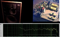
Here the speaker system with current mid/hf and uhf passive crossover and in room response measurement, a diy version of a large 4 way JBL 4345. The biamplification crossover is at 290 hertz with a 3rd order slope.
The network attenuates the mid cone driver about 5 db, the horn about 12 db and UHF driver about 10 db. So there is considerable wastage of class A watts with the X Aleph currently used to drive the system in full passive mode.Eventually I will run it fully active.
macka
The network attenuates the mid cone driver about 5 db, the horn about 12 db and UHF driver about 10 db. So there is considerable wastage of class A watts with the X Aleph currently used to drive the system in full passive mode.Eventually I will run it fully active.
macka
Attachments
stefanobilliani said:Hello Macka,
Very good stuff!
I just can't avoid myself to ask where you purchase all the 2sk .
Thanks
I didn't as it turns out, I asked a special diy friend in the trade and they arrived in the mail without paperwork despite my insistence.
Must have just slipped through and best left a secret.
macka

promitheus said:How is it going ?
Really would like to see some pictures.
I want to make something like that soon.
Yeah, Yeah .....
You need to be more specific? Nelson's kitchen table?
I cropped mine out for this image, drilling a pcb on her indoors table could be dangerous.
There's lots of holes in this board, so much so I went and bought a new camera to prove it.
I've done the daughter boards and about half way on the mother board. Can't wait to fire it up. Building a new X Aleph 75+75 for the bi amp show.
macka
Attachments
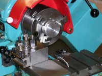
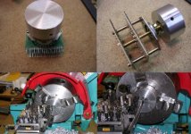
Here I digress slightly.
A short excursion to my fathers garage for some how to skills on making some knobs. I should have one finished tomorrow.
Its actually not that simple and we created quite a detailed drawing before commencing the cutting. The diameter will be 48 mm finished and 25mm deep, the rear recess is 20mm x 4 mm deep.
I plan to use these with the Electro switches (kindly sent to me by Nelson) on the BOSOZ and a slightly smaller version on the High Low Pass.
macka
Attachments
A bit of progress here,
Had to order the Dales from Allied, freight was a killer but no choice.
I am a bit miffed by R28/R29 (10K), can't find it on the filter layout.
(R10/1 appears to be the same part but 4.7K)
Perhaps Moamps can enlighten me.
Ian
Had to order the Dales from Allied, freight was a killer but no choice.
I am a bit miffed by R28/R29 (10K), can't find it on the filter layout.
(R10/1 appears to be the same part but 4.7K)
Perhaps Moamps can enlighten me.
Ian
Attachments
- Status
- This old topic is closed. If you want to reopen this topic, contact a moderator using the "Report Post" button.
- Home
- Amplifiers
- Pass Labs
- My High Low Pass