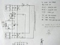
That's the schematic for AC connection I used in my A75 amps. The circuit around 2 bridges is taken from ML23 amp and supposed to remove DC component from the power line and prevents transformer saturation. Can somebody explain how it works and is it worth to install it?
Attachments
I haven't taken a close look at this filter, but check out this thread for some insight:
http://www.diyaudio.com/forums/showthread.php?threadid=2080
http://www.diyaudio.com/forums/showthread.php?threadid=2080
I used the same exact circuit topology for my stereo Leach SuperAmp except that it used a single bridge rectifier. The triac is actually used as the main switch. The R and the C around it are used to snub the switching triac's transients. The physical switch puts the AC line on the gate of the triac which forces it to work within the first and third quadrants. Everything else should be recognizable. I would not encourage its use even though I used it. The problem with this type of circuit is that the brief switching transients of the triac often appear out of the noise in the audio. So it leaves a tiny bit of noise. And you can see it on the scope too it you look at it. Little tiny spikes only a few millivolts rising out of the noise positive and negative 120 times per second. However, it is an easy way to turn on the primary of the transformer without using a huge ugly industrial size power switch. I used a small signal switch mounted on the front to trigger a relay to trigger the gate. Thats my experience: advantages and disadvantages.
BeanZ
BeanZ
Harry:
Could it be that their using the resistors and capacitors to create a phase difference in the ac and using the bridges as a sort of trap because of that difference. The center of the bridge looks like a dead short perhaps unless the small amount of ripple is out of phase, in which case would some cancellation occur? I really don't know, I'm just kicking some ideas around. Must have been invented when Reagan was in office. A kind of VooDoo Elecotronics Good luck in your quest, it's over my head
Could it be that their using the resistors and capacitors to create a phase difference in the ac and using the bridges as a sort of trap because of that difference. The center of the bridge looks like a dead short perhaps unless the small amount of ripple is out of phase, in which case would some cancellation occur? I really don't know, I'm just kicking some ideas around. Must have been invented when Reagan was in office. A kind of VooDoo Elecotronics
Good luck in your quest, it's over my headIt looks a bit strange but the fundamental idea appears to be the same as those older type amplifiers that use a single supply rail and an output coupling capacitor to remove the half-rail dc offset before it gets to the loudspeaker. Instead of the speaker being driven zero to full rail, the capacitor causes it to be driven +half rail to - half rail.
Even if the waveform fed to the cap is assymetrical, the cap ensures the waveform fed to the speaker has the same area above zero as below zero. So the average dc output is zero i.e. just what you and the speaker want. Unless of course you are also trying to reproduce the barometric pressure on the day of the concert.
This circuit does the same thing. It guarantees the transformer is driven equal volt/seconds (i.e. area under the half cycle) positive and negative.
The bridges are arranged like a pair of back-to-back zeners across each cap, limiting the cap voltage to about + - 1.5 volts either polarity so you could use a high value low voltage cap. Looks like TH at the top is a thermistor for inrush reduction. I can't see why the lower caps & bridge are needed, it is a series circuit so one set would be enough.
As for why you might need one of these, the transformer out in the street won't feed you dc as such, that's impossible, but someone else might be using some sort of load that distorts the ac by pulling unequal pos and neg current therefore the line voltage may not swing equally pos and neg. The difference appears as dc and flows straight through your transformer primary. Your tranny usually won't have an airgap in the core so it will very easily saturate, maybe even burn out at part load only.
GP.
Peter I like to see your progress. Maybe I am also going to use your AC power connection within my AlephX. After I studied the schematic I have a few questions. If I am correct four fuses are drawn in the schematic. When I look at your photo I see only two fuses.
1) Did you skip the fuses in the primaries?
2) What triac did you use?
Marco Ensing
1) Did you skip the fuses in the primaries?
2) What triac did you use?
Marco Ensing
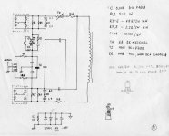
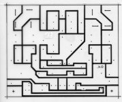
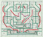
Since there is an interest I post bettter pic of it. The schematic is based on A75 AC connection and ML23.5 DC removal circuit. I used 2 fuses closer to AC socket. The circuit worked very well for me over the years. Triac is DigiKey part# Q6040J7. Most of the values are given on schematic. The small circuit below is used for connection between amp's ground and chassis and is also placed on a board.
Attachments
Most often the source of the DC is the Triac, which is why
I don't use them.
Even if you don't use a Triac, there might be a lamp dimmer
or a hair dryer on the circuit somewhere that does, and
so DC blocking is often necessary to keep the toroidal
transformer's mechanical noise down.
You will see this more and more, as the lines appear to
be getting dirtier with time.
Bridge rectifiers in the AC line for blockage cannot be relied
upon that well, and the best solution is two of them in series,
paralleled with the back to back electrolytics.
Actually just a nice fat pair of electrolytics is up to the task.
That circuit was built in 1995 after the A75 article, which was using triac for switching. I was wondering if I should remove it, because someone already suggested that it may be a source of noise as well. Any comments on that? I could replace it with 110V relay. Is it worthwile?
Banned
Joined 2002
If you are concerned that the triac is the source of DC at primary, you shouldn't. I've built 4 amps using that circuit, and they are extremaly quiet when it comes to transformer behaviour (which was not always the case on my other amps without that circuit).
The only thing I might be concerned at this point is if the triac might generate some unwanted noise after initial switching on.
The only thing I might be concerned at this point is if the triac might generate some unwanted noise after initial switching on.
blocking DC from tranny primary
Nelson's comments reminded me of a circuit I posted a while back. Rumor has it the circuit posted here does a great job of removing DC on the line. It's pretty simple, too!
I use relay shorting a 10ohms (or so) resistor in the transformer primary circuit for my power-on surge limiting. Works great for 1200VA tranny (with lots of energy storage in the supply). Originally (over 15 years ago) used the 555 to control the relay (I had LOTs and needed to get rid of some) and later (about 7 years ago) changed to the Elektor circuit. My delay time is 5-10 seconds.
mlloyd1
Nelson's comments reminded me of a circuit I posted a while back. Rumor
has it the circuit posted here does a great job of removing DC on the line. It's pretty simple, too!I use relay shorting a 10ohms (or so) resistor in the transformer primary circuit for my power-on surge limiting. Works great for 1200VA tranny (with lots of energy storage in the supply). Originally (over 15 years ago) used the 555 to control the relay (I had LOTs and needed to get rid of some) and later (about 7 years ago) changed to the Elektor circuit. My delay time is 5-10 seconds.
mlloyd1
Nelson Pass said:.....the best solution is two of them in series,
paralleled with the back to back electrolytics.
...
Actually just a nice fat pair of electrolytics is up to the task.
A simmilar advice from another thread:Nelson Pass said:Most often the source of the DC is the Triac, which is why
I don't use them.
Even if you don't use a Triac, there might be a lamp dimmer
or a hair dryer on the circuit somewhere that does, and
so DC blocking is often necessary to keep the toroidal
transformer's mechanical noise down.
You will see this more and more, as the lines appear to
be getting dirtier with time.
Bridge rectifiers in the AC line for blockage cannot be relied
upon that well, and the best solution is two of them in series,
paralleled with the back to back electrolytics.
Actually just a nice fat pair of electrolytics is up to the task.
I want to apply the back-to-back electrolytics as recommended, but after a bit better understanding of the background. The b-t-b will make a status of equipotential polarities of dielectric materials, and so the voltage rating of the electrolytics will be no more care. The current rating will be the only care for the use of the b-t-b. Is my understanding in the way?If you are experiencing mechanical hum from your
transformer, it is often caused by the presence of
DC on the line. Usually this comes from some appliance
using current asymmetrically, such as a lamp dimmer.
The hum comes usually from toroidal transformers, which
saturate easily with DC, and when they recover, they
draw an extra pulse of current, causing the noise.
You can put a pair of back-to-back electrolytics in series
with the AC power line to block this, and it works fine.
Makes sure the current rating of the electrolytics is
high enough, and the they are joined at a like polarity,
such as + to +.
Thanks for your response.
JH
Hi Peter,
as you invited to this thread...the schematic confuses me.
It is from a commercial amplifier?
There are four fuses in series to protect one transformer primary and some circuit. Load current will pass them one after another.
With ideal fuses, the 8A will blow rendering the others useless.
Within real world just anyone of them will blow, but leaving the others useless as well.
Certainly I'm missing something. But what?
Regards
Jürgen
bridge limit voltage 1 to 1.4 v
-in your case 10,000uF + 10,000uF = just 5000uF
-in my case 10,000uF // 10,000uF = 20,000uF
-Xc of 20,000 X my aleph 3 2A = ~ .35v and bridge
limit to 1 to 1.4 it s ok but in your case attention
to check that maybe .5v on 5000uF is max.
to be safe
-in your case 10,000uF + 10,000uF = just 5000uF
-in my case 10,000uF // 10,000uF = 20,000uF
-Xc of 20,000 X my aleph 3 2A = ~ .35v and bridge
limit to 1 to 1.4 it s ok but in your case attention
to check that maybe .5v on 5000uF is max.
to be safe
Attachments
- Status
- This old topic is closed. If you want to reopen this topic, contact a moderator using the "Report Post" button.
- Home
- Amplifiers
- Pass Labs
- AC power connection schematic explanation needed