Beautiful (?) 3D electronics
Whilst I've often used p2p for RF and microwave prototyping with excellent results, when doing critical analogue electronics at lower frequencies I have no doubt whatsoever that a good PCB layout will outperform p2p.
My own recent work in ultra low noise PSU's has shown me that physical connection points are critical, I can guarantee absolutely the position of a track on a PCB, and exactly where it connects, but the only way to acheive the same result with p2p, is a hot soldering iron, and moving wires and then measuring the result (or by doing something much more messy).
Those bus-bars in your photo for example aren't true summing points for the current flows in them - does that affect performance in any way? Each o/p device sees different potentials, related to the current flow in the finite impedance of the wires. It may not be relevant, but I doubt, if all else were optimized, that would be the case.
I personally like the inside of the case to look as good as the outside - p2p will never achieve consistent results - you cannot control the stray parameters in the way a PCB can, I'd go for a PCB every time, despite the aggravation.
A.
a good PCB layout will outperform p2p.
For really serious high audio I do not agree.
1. It is probably easier to get better quality wire than the quality of copper used in printed circuit material. Particularly for large conductors. I believe for four ounce copper PCBs they often plate up 1 or 2 ounce copper base material to four ounce. This leaves plenty of chance for contamination. I know. I have spent plenty of time in board shops. Solder mask over bare copper, the board are often plated in then the plating chemicaly stripped.
2. Dielectrics.... Go ask for teflon and if the guy running the board shop doesn't throw a fit, proceed to your bank to check your balance cause you are going to pay big time. Teflon insulated wire... real common.
3. There are many high end products that use point to point wiring or a hybrid of PCB boards and wire. Think they enjoy paying for the extra labor. Maybe there is good reason to do it and price the product to take account of this increased labor cost.
4. Flexibility... it is easier to change wiring routes and guage than spin a new PCB. Same goes for circuit changes. And I have modified hundreds of PCB based designs so I speak with experience.
5. PCBs are great for mass production, but some of us build race cars and not Toyota Camerys around here. Try both methods on your next serious audio project and you may be suprised. I have cut traces to run long and or critical signals with wire many times with good results. I think hand wired circuits look just as cool as PCBs.
H.H.
Banned
Joined 2002
Banned
Joined 2002
The A-40 point to point picture is at
http://www.passdiy.com/legacy.htm then reed the A-40
project.
Regards,
Woody
http://www.passdiy.com/legacy.htm then reed the A-40
project.
Regards,
Woody
Nednai said:I’d recommend using a self-reversing Tapmatic with a drill press instead of a drill gun with a clutch. I’d even suggest using drill guides with a drill press instead of drill guides and a drill gun.
I tried Tapmatic with drill press and I will never use it again on heat sinks and small amplifier parts. Forget about that thing when tapping 7/64" holes. You don't need drill guides when using drill press. When your part is on the table the drill is always aligned properly. Drill guides blocks are designed to be used with hand drill guns. If you never tried cordless drill gun with a clutch for tapping I recommend you try. You will not believe the results and forget about Tapmatic.

Re: Beautiful (?) 3D electronics
I don't quite follow what you are trying to say here. Whould you make better bus-bars with PCB? You cannot say that they don't have the same potential if you don't see where the power supply is connected and it is not connected yet.
Actually what you see on the photo is a prototype which will be tested and optimized depending on performance. What I probably would do is to provide ea. output device with it's own capacitor bank connected directly to the device. On the other end ea. capacitor bank would be connected to the rect. bridge and that's where the main buss is going to be. I know that the best way would be star connection with separate wire from bridge to ea. capacitor bank. That way I will not have a buss as such between devices.
ALW said:Those bus-bars in your photo for example aren't true summing points for the current flows in them - does that affect performance in any way? Each o/p device sees different potentials, related to the current flow in the finite impedance of the wires. It may not be relevant, but I doubt, if all else were optimized, that would be the case.
A. [/B]
I don't quite follow what you are trying to say here. Whould you make better bus-bars with PCB? You cannot say that they don't have the same potential if you don't see where the power supply is connected and it is not connected yet.
Actually what you see on the photo is a prototype which will be tested and optimized depending on performance. What I probably would do is to provide ea. output device with it's own capacitor bank connected directly to the device. On the other end ea. capacitor bank would be connected to the rect. bridge and that's where the main buss is going to be. I know that the best way would be star connection with separate wire from bridge to ea. capacitor bank. That way I will not have a buss as such between devices.
Re: ... a clutch for tapping ...
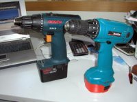
This is what I'm talking about. Both those pistols are available from Home Depot and they have build in clutches. I don't think you can get a clutch separately. For construction work I prefer Makita, for fine metal work on amplifiers I chose Bosch, 12 V should be enough. And don't listen to people who tell you that Tapmatic tool is better.
fcel said:Peter: I know I've seen your pictures and description of clutch for cordless drill for tapping purposes. Can I get the clutch that you mentioned from Home Depot? Part #? Is there different sizes? Thanks.
This is what I'm talking about. Both those pistols are available from Home Depot and they have build in clutches. I don't think you can get a clutch separately. For construction work I prefer Makita, for fine metal work on amplifiers I chose Bosch, 12 V should be enough. And don't listen to people who tell you that Tapmatic tool is better.
Attachments
Don't stop the DIY
Whether PCB or p2p is better for the bus-bars is irrelevant. You can only connect the power to one point on each bar and it matters little where that is, the original statement holds true. Simple ohms law dictates it must be so.
Wherever you connect it the different devices will see different potentials, and modulations theroeof, effects can be minimised with care, something I'm sure you've already thought about.
As I said it may not matter, but have you tried alternatives, or examined the effect?
As for your other comments: -
1. It is probably easier to get better quality wire ...
This is relevant if you consider it to be important to the final result. PTFE dielectric PCB is not cheap or pleasant to work with, but I do not believe that FR4 is going to have a serious detrimental effect. It's used in just about every high-end product I can think of. In p2p the dielectric is primarily air (unless laid in contact with a chassis, I'm not convinced the dielectic's electrical properties are relevant. Mechanical - maybe.
2. Dielectrics.... see above
3. There are many high end products that use point to point wiring or a hybrid of PCB boards and wire. Think they enjoy paying for the extra labor. Maybe there is good reason to do it and price the product to take account of this increased labor cost.
OR maybe need a justification for the often exhorbitant price
One will always need a limited amount of wiring, and I can think of loads of instances where it's easier to get a desired result using mixed technology, so no real disagreement there.
4. Flexibility... it is easier to change wiring routes and guage than spin a new PCB. Same goes for circuit changes. And I have modified hundreds of PCB based designs so I speak with experience.
There is one big proviso to this though - that is the original PCB designer got it wrong!
If the PCB was right and optimized in the first place, there would be no need to mod. I now spend inordinately large amounts of time designing and simulating real models of my work - I can usually get most things right first time then. Mods only then come from technology improvements.
5. PCBs are great for mass production, but some of us build race cars and not Toyota Camerys around here. Try both methods on your next serious audio project and you may be suprised. I have cut traces to run long and or critical signals with wire many times with good results. I think hand wired circuits look just as cool as PCBs.
I wouldn't let p2p anywhere near a race car
My PSU's are pretty much as good as it gets (Jung-based). I know for a fact it would be impossible to get consistent and almost perfect results without a PCB. Of course there's plenty of wiring to the PCB's. A wire though, 1mm out of place, even along a heavy low-impedance connection gives measurable and audible degradation!
My over-riding comment is that you simply cannot consistently control any of the parameters needed for good, performance using p2p, mechanical and electrical properties will change in every unit you build.
None of the above is a personal criticism, p2p is a great way for most people to do DIY, something I'd never discourage, and for 1 off's you may get great performance, but try building a batch and getting exactly the same performance from each unit.
They say beauty is in the eye of the beholder, but in p2p I just think 'rats nest' .
A.
Whould you make better bus-bars with PCB? You cannot say that they don't have the same potential if you don't see where the power supply is connected and it is not connected yet.
Whether PCB or p2p is better for the bus-bars is irrelevant. You can only connect the power to one point on each bar and it matters little where that is, the original statement holds true. Simple ohms law dictates it must be so.
Wherever you connect it the different devices will see different potentials, and modulations theroeof, effects can be minimised with care, something I'm sure you've already thought about.
As I said it may not matter, but have you tried alternatives, or examined the effect?
As for your other comments: -
1. It is probably easier to get better quality wire ...
This is relevant if you consider it to be important to the final result. PTFE dielectric PCB is not cheap or pleasant to work with, but I do not believe that FR4 is going to have a serious detrimental effect. It's used in just about every high-end product I can think of. In p2p the dielectric is primarily air (unless laid in contact with a chassis, I'm not convinced the dielectic's electrical properties are relevant. Mechanical - maybe.
2. Dielectrics.... see above
3. There are many high end products that use point to point wiring or a hybrid of PCB boards and wire. Think they enjoy paying for the extra labor. Maybe there is good reason to do it and price the product to take account of this increased labor cost.
OR maybe need a justification for the often exhorbitant price
One will always need a limited amount of wiring, and I can think of loads of instances where it's easier to get a desired result using mixed technology, so no real disagreement there.
4. Flexibility... it is easier to change wiring routes and guage than spin a new PCB. Same goes for circuit changes. And I have modified hundreds of PCB based designs so I speak with experience.
There is one big proviso to this though - that is the original PCB designer got it wrong!
If the PCB was right and optimized in the first place, there would be no need to mod. I now spend inordinately large amounts of time designing and simulating real models of my work - I can usually get most things right first time then. Mods only then come from technology improvements.
5. PCBs are great for mass production, but some of us build race cars and not Toyota Camerys around here. Try both methods on your next serious audio project and you may be suprised. I have cut traces to run long and or critical signals with wire many times with good results. I think hand wired circuits look just as cool as PCBs.
I wouldn't let p2p anywhere near a race car
My PSU's are pretty much as good as it gets (Jung-based). I know for a fact it would be impossible to get consistent and almost perfect results without a PCB. Of course there's plenty of wiring to the PCB's. A wire though, 1mm out of place, even along a heavy low-impedance connection gives measurable and audible degradation!
My over-riding comment is that you simply cannot consistently control any of the parameters needed for good, performance using p2p, mechanical and electrical properties will change in every unit you build.
None of the above is a personal criticism, p2p is a great way for most people to do DIY, something I'd never discourage, and for 1 off's you may get great performance, but try building a batch and getting exactly the same performance from each unit.
They say beauty is in the eye of the beholder, but in p2p I just think 'rats nest'
.A.
Re: Don't stop the DIY
ALW said:
Whether PCB or p2p is better for the bus-bars is irrelevant. You can only connect the power to one point on each bar and it matters little where that is, the original statement holds true. Simple ohms law dictates it must be so.
That could be avoided with star wiring where you run separate wire to ea. device from power supply point, same for all devices. Something that could be practically impossible with PCB and really easy with p2p, even with 24 output devices.
Any thought on that?
We are not talking about repeatibility here also, because ea. amp is more like piece of hand made art with a unique value for its owner.
Those heat sinks are huge compared to the small parts I had to tap using a Tapmatic. We always used a clamped drill guide and a drill press. Without a mill, it was the quickest, easiest way to get accurate drilled holes, which was required to get FAA certification. After drilling/tapping 10’s of thousands of holes using drill guns and drill presses, I’m surprised you had difficulty with a press, even at 7/64”. I guess the ease came with experience.
Whenever possible I always use press drill to drill holes. Even size 70 drill doesn't present any problem. I never use clamps and guides on drill press because I'm not required FAA certification and it slows my work. When not using drill guides, clamp is actually not recommended because without it a drill centers better on a piece you are drilling.
Remember that we are talking here about DIY and most of the people don't have access to Tapmatic and drill press. Even mine is only 8" and some of the holes on that big heat sink I couldn't drill on drill press. The only alternative is using hand drill (alhough for that purpose I don't recommend cordless one because the speed is too slow, use electric one) and a guiding block I showed in a picture before. Most of the people don't have access to commercial ones but one can be easily made as I also show in a picture as well.
I tried Tapmatic before and didn't like it. Used to tap everything by hand. Just recently tried to use a cordless drill and I am surprised with results. And it also much faster. Ever tried tapping M2 on Tapmatic?
Actually, you clamp the guide to the piece you’re drilling. I didn’t notice any built in clamp on your guides. When a guide costs $10-15, why make one at home? As for certification, I’ve never known an FAA certified driller/tapper. It’s the parts that get certified. M2 on a Tapmatic? No problem. When a press&Tapmatic costs less than a new Weller, why not have them? Easy, precise, fast, who would want less?
When you use hand drill do you also clamp the guide to the piece you are drilling? Because you really don't have to. I'm using mine on aircrafts and it's impossible to clamp them to the skin. That's why you don't see them on my guides.
Would you mind leting everybody know where those cheap guides can be obtained? I guess they might be handy for everybody drilling holes in heatsinks.
I also don't understand your argument. I presented here something very simple and it works so why make it more complicated?
Would you mind leting everybody know where those cheap guides can be obtained? I guess they might be handy for everybody drilling holes in heatsinks.
I also don't understand your argument. I presented here something very simple and it works so why make it more complicated?
- Status
- This old topic is closed. If you want to reopen this topic, contact a moderator using the "Report Post" button.
- Home
- Amplifiers
- Pass Labs
- The beaty of p2p wiring