DIGORA said:
It can work in class AB ?
Yes.
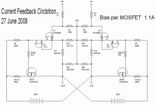
The patent(4229706) refers to the diodes-resistors
(D1 R6 D2 R7, my schematic) connections as to help operate the circuit in class B.
I assume this can apply to class AB operation also.
Tom
To continue the discussion of a F5 like current feedback circlotron :
http://www.diyaudio.com/forums/showthread.php?postid=1549534#post1549534
This would have been the circuit I would have proposed. I don't think it matters whether we use 2SK170 or 2SK369. I do think the J111 cascode is necessarily.
But I am also puzzled by Klaus's simulation results. Need to think first.
Patrick
Attachments
Klaus,
I presume you were using balanced input signals.
http://www.diyaudio.com/forums/attachment.php?s=&postid=1549499&stamp=1214589765
http://www.diyaudio.com/forums/attachment.php?s=&postid=1549502&stamp=1214590037
Could you show plots of V across R6 and Vgs across J2 alongside the input signal ?
Thanks,
Patrick
Patrick,
Yes, I used pefectly balanced input (which is also quite important, of course).
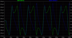
Here Vgs at J2 (green) and Voltage accross R6 (blue). Not very nice at all....
Hhm, you might want to install LTSpice yourself, this makes evaluation much easier (models used for the transistors are found here on this forum, the JFETs were posted by syn08 and the MOSFETs by andy_c).
- Klaus
Attachments
EUVL said:...
This would have been the circuit I would have proposed. I don't think it matters whether we use 2SK170 or 2SK369. I do think the J111 cascode is necessarily.
...
Patrick
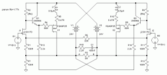
Patrick's schematic as .gif file:
Attachments
Thanks for converting to gif.
I just discover a mistake. The batteries should be the other way round.
Sorry guys.
Patrick
PS I believe I might have an explanation for the wild common mode bias swing, which is (mainly) at twice the frequency of the signal, but I do not have a cure yet. Need more thinking.

I just discover a mistake. The batteries should be the other way round.
Sorry guys.
Patrick
PS I believe I might have an explanation for the wild common mode bias swing, which is (mainly) at twice the frequency of the signal, but I do not have a cure yet. Need more thinking.

Attachments
Seems that I found a remedy, maybe not the most elegant but it's working:
Buffering the gate drive with the right type of buffer (I missed this in my first try). This buffering also would help thermal compensation and is compatible to the current limiting (mabye a base reverse bias protection diode is needed). Freq. compensation seems necessary as the buffer unloads the resistors, I tried here this time with slightly inductive source resistors and an output snubber. It appears to be stable with capacitive loads in the nanofarads range and no resistive load (the situation when a cable is attached but not the speaker itself).
Now, at 20kHz, that common mode modulation is almost gone (reduced by the buffer's current gain) and the circuit behaves well and has good perfomance. Still it is not very intuitive what the root cause was, originally. At any rate, both capacitive gate currents got routed somehow through both resistors because the return points of these currents were on the "wrong side" of the load.
Matching of R7 to R12 is very critical... or a point where any mismatch introduces even order distortion if that is wanted. Other parameters seem less critical wrt matching.
Last not least, I'm very curious to see mrothacher's circuit....
- Klaus
Attachments
Klaus,
If my head is functioning properly today, then your first circuit should work without this common mode current problem :
http://www.diyaudio.com/forums/attachment.php?s=&postid=1547137&stamp=1214344739
The only change I would perhaps make is to refer R12,13 (100k) to Gnd, and cascode the JFETs. It is a bit difficult to explain, but it is to do with even harmonics of the input JFETs when driven by a differential signal, which would result in common mode currents flowing to Gnd, whereas the odd harmonic content of this current will cancel each other as they are of opposite polarity.
In the circuit by Circlomanen e.g., this JFET common mode current (at say 2x signal frequency) flows through the 22R resistor (& the 2200u cap) towards ground, then through the 100R output load resistor of the opposite leg, and then back to the power supply. This in turn creates a negative common-mode voltage at both outputs which is fed back to the JFET gate via the feedback resistor, ending up as positive feedback.
The solution would then be to connect the 22R resistors to each other (without the caps) and lift them from Gnd. This way, the JFET current is forced to flow through the feedback resistors and the load resistors before completing the loop to the power supply, and thus any positive common mode current will lead to an increase in JFET source voltage (i.e. returning back to negative feedback).
There should still be a very small common mode current at 2x signal frequency, but it should not be more than a few mA.
I don't have DSL at home, so I am not downloading LT Spice this weekend to prove my hypothesis. But I think this matches what you showed in the JFET and MOSFET currents.
Attached my new proposal.
Patrick
Attachments
Hi Patrick,
I see you went through the same mind-boggling "in-the-head evaluation" horrors...
To cut things short, I found that the major contributor to the effect is the high and varying Cgd of the MOSFETs, that is, when I disable Cgd in the MOSFET models, et voíla, all is fine. The JFETs contribute to a far lesser amount. I virtually went through dozens of different hookups (including cascoding etc) but the most effective way to block the capacitive current flow in the JFET drain resistors is to buffer them with a follower in the way I've shown. The way feedback is arranged seems not to be important to the effect, meaning that your last proposal (which was my initial one) doesn't fix the problem, according to my findings.
How important this issue is in real life is still another matter since we don't expect a 10kHz or 20kHz full scale signal anyway (the tweeters will thank it). OTOH those two followers are an easy fix...
Finally, compared to the F5 the performance doesn't seem to be any superior, only added complexity (not least the supplies). The F5 is really hard to beat and that's why Admiral Nelson is the Master.
I like this quote of him very much:
"Like the products of other young designers, my first commercial product had everything but the kitchen sink in it. Now I strive to be like Picasso, who could draw a woman with a single pencil stroke and create a masterpiece."
- Klaus
Thank you for this information. Maybe this is an appropriate solution for my question aboutYour link sends me to main page.
I looked through the web site and found it?
Is this it?
Hopefully the attached schematic works.
http://www.diyaudio.com/forums/soli...iragas-le-monstre-circlotron.html#post2551568
- Status
- This old topic is closed. If you want to reopen this topic, contact a moderator using the "Report Post" button.
- Home
- Amplifiers
- Pass Labs
- Experimental Design - Comments, Flames Welcome


