wire size
I'm afraid I can't provide any direct ideas for you, but I noticed your comment about 22GA vs. 14 GA wires on the input common.
Yes, there is a big difference between 14 and 22.
Cross sectional area of 22 GA is about 1/64th of 14, and resistance is about 6x greater.
I would think that it should not matter since there shouldn't be any appreciable current flowing in the input ground circuit. But that may be a clue, since the hum increases when you increase the wire size (if I understand you correctly).
I got the info from http://www.tpub.com/neets/book4/11c.htm
By the way, if you're in the US, consider a scope from ebay. You can get one that will do the basics for under $100, and a very good one for $200 or less.
sounds like a ground loop. have you tried connecting 10 ohm resistor to leave the ground. i can't remember where is best to connect the resistor. try connecting at signal ground to mains earth. Can't really remember. On the scope to cure hum, a scope might do some help. The main thing that can cure a hum is patience and guidance and luck. Great combination. Try out different solutions and hope for the best.
WOW!!
I HOPE SOMEONE READS THIS, I WOULDN'T BLAME YOU ALL IF YOU'D GIVEN UP ON ME.
HUM GONE
MUSIC GREAT
ME HAPPY
I USED THICKER WIRE FROM THE INPUT GROUND TO EARTH AND ALSO A CONNECTION TO THE PCB GROUND.
SORRY IF THAT HAD ALREADY BEEN SUGGESTED AND I'D NOT CAUGHT IT.
I REALLY WANT TO THANK THIS FORUM, THE PATIENCE AND ATTENTION THAT HAS BEEN AFFORDED THIS NEWBIE THAT, AS MENTIONED BEFORE IN OTHER THREADS THAT WAS IN OVER HIS HEAD!
I'VE REALLY LEARNED ALOT HERE, MORE THAN I THOUGHT POSSIBLE.
THANKS AND I'LL TRY TO FORWARD SOME PICS WITH PARTICULARS ONCE I GET THIS BEAST REASSEMBLED.
CHEERS,
SCOTT
Quote "............ AND ALSO A CONNECTION TO THE PCB GROUND"
Scott,
Are you saying that you did not have the ground wires to the main pcb all this time? Or you're saying you're using thicker ground wires to the main pcb?
I do remember there wasn't a ground "plate" for the Aleph 2 main board and thus requires two (input & output?) ground wires to the board ... or something like that.
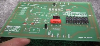
Here's a pic of the board.
Scott - Did you have GND wires from each of the two GND vias tied to your star ground? It sounds as if you ran your input grounds only to your star ground and not also to the board. It shouldn't have mattered unless the GND wire on the input side didn't have a good connection or your star ground was floating... Is this correct? Lastly, was your star ground also earth (chassis) grounded?
I'm unclear on exactly what you changed????
Thanks,
Steve
Attachments
Scott,
Can you post some pictures of your working amplifier? or e-mail them to me at: gte619j@prism.gatech.edu
I am interested to see your finished amplifier.
--
Brian
gte619j@prism.gatech.edu
Can you post some pictures of your working amplifier? or e-mail them to me at: gte619j@prism.gatech.edu
I am interested to see your finished amplifier.
--
Brian
gte619j@prism.gatech.edu
AND ALSO A CONNECTION TO THE PCB GROUND
Hmmm...... there seem to be two ground traces on the PCB with pads that would connect standoffs and/or mounting screws to the chassis ground. These grounds would only be tied together by
the mounting hardware unless delibrately and correctly wired together . Ground loops? Yes I think we can say that is a very real possibility......... Brian you want to help us out on the correct ground connections?
H.H.
well,
it's never so simple is it? one channel was working so i replaced C7 on the other channel and hooked up the wires and fired 'er up.
HUMMMMMMMM
so, i made dinner and calmed down to give it another go.
here's the current, and very quiet setup: (i don't know if it's correct, but if it's quiet it's good, no??)
- both ground busses on the main pcb are ganged and connected to the star, along with the cap ground, center taps.
- the negative, or ground on the amp input is tied to the board ground AND to the mains earth ground with a heavy cable.
this is for one channel, the other channel is wired the same.
and it is crystal clear. with only a slight hum with my ear to my test speaker.
hope that helps clear it up.
brian, i'll get some pix over to passlabs diy this weekend.
not really sure why it's working well. i do think that the thick ground going to my mains earth is helping rout any crap out, back into the plug ground.
thanks,
scott
Scott,
Glad to hear that you have resolved your oscillation and ground loop hum problems. Way to stick with it. I guess this means your amp isnt for sale. There were many good suggestions and yes a solution was suggested in the e-mail I had sent you.
"As far as grounding goes let me see if I understand how you have it configured. The input ground is isolated from chassis and attaches to the PCB ground. There is only one ground wire going to your star connection from the PCB. Your speaker ground, isolated from chassis, is connected to your star connection...."
You might give a summary of your trials and solutions so others may benefit from your learning.
BDP
bryan,
i'll be more than happy to post my trials and tribulations once i get this thing closed up, stable and happy. cuz that's all i want, a happy amp, cuz that makes me happy.
ground scheme as it sits now is a littel diff than you posted:
-the input ground, at the unbalanced input rca connector, goes to the pcb AND to my earth/chassis ground (my ntc and ac ground is there as well).
-the input ground is attached to the pcb grounds in a sort of three-way, then a lead connects these to the star ground that is floating, along with the filter cap grounds and the center taps.
to be honest, i'm not completely sure why it worked the way it did, but unless there are any serious concerns, i'll let it be.
and, no, the amp is not for sale. that's a whole other story, in a nutshell, i thought i was in over my head and figured that someone would love to get their hands on an almost complete diy amp. i now think that that defeats the purpose of diy. and it 's very frustrating working on a piece of equipment that you don't really understand.
i won't consider this a success until it's been up for a week or so (just long enough to burn up my output mosfets).
hope this answers some questions
cheers,
scott
Scott -
As I read your description, your PCB and star ground are being tied to the earth ground via your input ground wire following back through the main GND trace on that side of the board then down to the star ground... Is this correct?
On the board itself, the input ground is tied to the main GND trace on that side of the board...
Why not just tie your star ground and your earth grounds together? I think your floating star ground was your problem. Have you tried this?
To everyone else, is there a problem with doing this???
Thanks,
Steve
- the negative, or ground on the amp input is tied to the board ground AND to the mains earth ground with a heavy cable.
As I read your description, your PCB and star ground are being tied to the earth ground via your input ground wire following back through the main GND trace on that side of the board then down to the star ground... Is this correct?
On the board itself, the input ground is tied to the main GND trace on that side of the board...
Why not just tie your star ground and your earth grounds together? I think your floating star ground was your problem. Have you tried this?
To everyone else, is there a problem with doing this???
Thanks,
Steve
steve,
if you're talking about connecting my star ground to the earth, i did that way back when i initially started this project, and it started to melt my center tap leads, so i stayed away from that. not sure WHY they heated up, i can't remember the exact way it was all tied together, but that's why i abandoned that route.
if it's more desirable, maybe i could change it around.
thanks,
scott
If I'am following this correctly there is no connection being made from star ground to Earth or chassis. For safety the thermister is there to give you a low enough resistance to chassis or Earth between your star circuit ground to prevent you from getting shocked in case some fault would occur. At the same time the thermister is there also to give some resistance or isolation from ground loops.
You might take a closer look at the A75 article. It lays the grounding scheme out quite well.
BDP
You might take a closer look at the A75 article. It lays the grounding scheme out quite well.
BDP
well,
the star is connected to earth sort of. kind of upstream as it were. working backwards from the star ground, a wire connects back to the pcb, to the input ground, and down to my chassis where it's hooked up commonly with the earth ground that goes up through my thermistor and finally hooked to the ac earth.
does that make sense (probably not)
I believe we are having some confusion as to what certain terms mean. Earth ground is what would come from the wall outlet. Chassis (your case) should be connected to this Earth ground. This is where the thermistor comes in. The thermistor would be connected from Earth/Chassis (same point) to star ground.
It seems to me that you could move the connection that is between input ground and Chassis, If we are calling them the same. Install it between your star connection and the thermistor. Of course you would still have your input ground going to the PCB ground and then your PCB ground would be going to the star connection and star connection going to the thermistor.
How does that sound, maybe we are saying the same thing. Hope this helps.
BDP
I was under the assumption from looking at the schematic and other designs that everything on the pcb would be tied to the star ground. The reason that there are two seperate grounds on the board, is that I simply did not route the two ground traces together. With all of the grounds from the pcb going to the star ground, then the earth ground from the wall outlet goes through a the thermistor, TH1 and then into the star ground. I assumed that nothing was tied directly to the earth ground. This would mean the the chassis itself is tied to the star ground.
Please correct me if I am wrong, as I would not want to confuse others.
On a side note, I am in France taking classes for the summer, and my responses might be quite delayed due to my plans here. Pictures of my summer are posted at: http://brian.darg.net/gtl/ As a side project, I am working on a redesign of the leach amp boards to use to-247 (or to-3p) devices in order to eliminate wiring. I have a bunch of friends who want leach amps, and with the new boards, it will make it a lot easier. Leach amps don't sound as good, but they are cheaper to make then class A amplifiers, and are not picky about parts. It also has great instructions and local school support for those who it is their first time amp.
--
Brian
gte619j@prism.gatech.edu
Oh no, #*x% I just read my last posting and Im incorrect in my last posting. Please disregard. I was strickly thinking about how the A75 ground scheme is configured. I guess I need a proof reader before posting. Maybe it was my medication or the late hour!!!. If the forum had a smirking red faced character I would paste it now. Sorry for any confusion I may have caused.
My point was that wouldnt it be best if the connection from input ground to Chassis be attached between the star connection and Chassis.
BDP
My point was that wouldnt it be best if the connection from input ground to Chassis be attached between the star connection and Chassis.
BDP
Aleph 2 Power Supply schematics
I myself have not built the Aleph 2 yet - I'm still trying to gather all the necessary parts - but since we're on the discussion of power supply, particulary on the subject of "hum", could somebody (Kristijin seems to be very good at this) redraw the schematic of the Aleph 2 power supply, especially in regards to star ground, chassis ground, earth ground, input ground and output ground so that some of us amateurs won't have to encounter this kind of potential problem when we're actually building the Aleph amps. Thanks.
I myself have not built the Aleph 2 yet - I'm still trying to gather all the necessary parts - but since we're on the discussion of power supply, particulary on the subject of "hum", could somebody (Kristijin seems to be very good at this) redraw the schematic of the Aleph 2 power supply, especially in regards to star ground, chassis ground, earth ground, input ground and output ground so that some of us amateurs won't have to encounter this kind of potential problem when we're actually building the Aleph amps. Thanks.
- Status
- This old topic is closed. If you want to reopen this topic, contact a moderator using the "Report Post" button.
- Home
- Amplifiers
- Pass Labs
- aleph hum