Hi all,
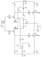
I have in my mind little project with minimal number of active elements. I need some help and advise – I am not a professional person in this matter. I know that this forum concerns Pass Lab products mostly, but what I want to build is very close to design philosophy here. I started from simulations in Spice and got a schematic, which I would to introduce. I have problem with THD figures, are very depended on the level of input voltage. All is very good for single mV and much worst for hundreds of mV. This is before clipping at the output, of course. Is the design has a sense and is worth to try?
I have in my mind little project with minimal number of active elements. I need some help and advise – I am not a professional person in this matter. I know that this forum concerns Pass Lab products mostly, but what I want to build is very close to design philosophy here. I started from simulations in Spice and got a schematic, which I would to introduce. I have problem with THD figures, are very depended on the level of input voltage. All is very good for single mV and much worst for hundreds of mV. This is before clipping at the output, of course. Is the design has a sense and is worth to try?
Attachments
Hi,
I like this kind of topology and I've been fiddeling with it some time, but that was more than a year ago. I is kind of similar to the ' Simple MJ amplifier' you can find on the net and on this forum. I remember posting a schematic very similar to yours. I got a good comment about the problem of inducing rimple via feedback network: you have done it better than me with the zeners. I also suggest decoupling the zeners with a parralel cap to exclude the non-liniear contribution of the zeners and limit the noise from the zeners.
As for the Iq and Voffset: you could use higher values source resistors.. 0R5 ? Or use a simple single transistor servo around the source resistors.
Liniearity should be pretty good, atleast in class A ( 1.5 Ampere minimum). 2Vrms watt THD should be less than 0.5%, but this is directly related to the load impedance, due to the common source output stage.
Goodluck, and keep us posted.
Thanks for your interest and help.
After reading your comments I understood there were same mistakes in my conception. I tried mix different ways of implementation in one circuit. Well, computer is very helpful but it will not replace a human thinking")
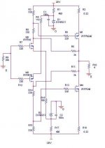
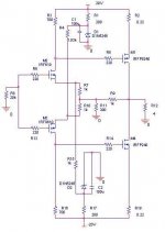
I was thinking it over and did two different versions of the schematic. Values of elements are only to start.
This is the first:
After reading your comments I understood there were same mistakes in my conception. I tried mix different ways of implementation in one circuit. Well, computer is very helpful but it will not replace a human thinking
I was thinking it over and did two different versions of the schematic. Values of elements are only to start.
This is the first:
Attachments
HEllo,
How or why did you come up with 100u for your caps? Why not 80u or why not 400u?
I noticed your MOSFETs are different numbers, for expample, one is 9640 the other is 640....is one an N-type and the other P-type...I'm being a little redundant here from my other thread on the X1000...forgive me.
How or why did you come up with 100u for your caps? Why not 80u or why not 400u?
I noticed your MOSFETs are different numbers, for expample, one is 9640 the other is 640....is one an N-type and the other P-type...I'm being a little redundant here from my other thread on the X1000...forgive me.
I is kind of similar to the ' Simple MJ amplifier' you can find on the net and on this forum.
Couldn't find.
 Any directions, please..
http://perso.wanadoo.fr/jm.plantefeve/sche.html
this page should be of interest too, especially the botttum circuit...
cu,
Thijs
this page should be of interest too, especially the botttum circuit...
cu,
Thijs
- Status
- This old topic is closed. If you want to reopen this topic, contact a moderator using the "Report Post" button.
- Home
- Amplifiers
- Pass Labs
- MOSFET/MOSFET amplifier